Goal detector for detection of an object passing a goal plane

a technology of goal plane and detector, which is applied in the field of goal detector for the detection of objects passing a goal plane, can solve the problems of high update rate, difficult to determine correctly, and the spatial and temporal resolution of video cameras is often not sufficient to provide the necessary information, so as to facilitate signal processing, improve output precision, and preserve the smooth surface of the goal

Inactive Publication Date: 2011-01-11
FRAUNHOFER GESELLSCHAFT ZUR FOERDERUNG DER ANGEWANDTEN FORSCHUNG EV
View PDF18 Cites 53 Cited by
  • Summary
  • Abstract
  • Description
  • Claims
  • Application Information

AI Technical Summary

Benefits of technology

[0017]The processing means process the output from all the antennas of the system, e.g. by calculating the sum and difference of the outputs of the antennas of each pair and calculate the ratio of the difference and the sum as described below. When this ratio is at its minimum, the radio wave emitter means passes the middle plane between the two antennas. The outputs from the two antennas of a pair may furthermore be calibrated for differences in magnitude of output, so that the ratio is zero at the minimum. The ratios obtained from all pairs of antennas are used to provide a common conclusive output and thereby compensate for uncertainties of the individual pair and maladjustments due to impacts during the sports game.
[0018]In a second embodiment, the radio wave emitter means is the plurality of pairs of antennas and the receiver is placed within the movable object. In a third embodiment, the first and second embodiment is combined to a system where the passage of the movable object is detected by both systems so that a higher reliability is obtained.
[0023]It is furthermore advantageous that the system of the invention comprises at least one stationary calibrator device emitting waves receivable by the antennas, arranged in the flat target plane to provide a calibration signal for the system. Thereby, a temporary or constant calibration routine may be performed by the system during use so as to compensate for changes in the position, orientation or other features of the antennas that are influential on their performance and output. The one or more stationary emitters are advantageously arranged on the goal. Alternatively, according to the second or third embodiment of the present invention, the stationary calibrator device may receive radio waves emitted from the pairs of antennas and provide an output accordingly to a control unit of the system. Supplementary or as an alternative to the calibrator device, each pair of antennas may be equipped with means, such as a dedicated receiver, for determining their position by means of a common positioning system, such as the satellite based Global Positioning System (GPS) so that deviations from the ideal positioning of the pairs of antennas may be detected and the evaluation of the system may be adjusted therefore.
[0024]In order to facilitate the signal processing and improve the precision of the output, i.e. the spatial resolution of the resulting output from the system, it is advantageous that each pair of antennas has a first antenna arranged in a first plane parallel to said flat target plane and a second antenna arranged in a second plane parallel to said flat target plane, wherein said first plane and second plane are common to all or substantially all pairs of antennas.
[0025]The radio wave emitter means and / or the receiver means of the movable object comprises in a preferred embodiment of the present invention antenna means that are regularly distributed in a shell of a shape corresponding to the outer shape of said movable object, so as to provide a homogeneous wave field with its centre in the middle of the object. In particular, it is preferred that the antenna means is arranged on the inner surface of the top layer material of said movable object. Thereby, a simple manufacturing may be performed with a high degree of precision so as to delimit the spatial uncertainties of the system.

Problems solved by technology

However, this may be very difficult to determine correctly in situations where the ball is returned quickly and has only just passed, or not passed, the goal plane, and it is particularly difficult if the referee is positioned unsuitably with respect to the goal plane or is engaged in other activity of the match.
Video camera may also be used to monitor the goal planes, but the spatial and temporal resolution of video cameras are often not sufficient to provide the necessary information in cases of doubt.
However, the determination of the passage of the goal plane is a very delicate matter, both because it may be decisive for the outcome of the sports match and because the distances are small and the velocity of the object often very high, so that a position determining system to provide a reliable determination of whether the object has passed the goal plane must be very precise in the determination of the position and at the same time have a very high update rate of the position determination.
The object may e.g. move with 72 km / h or 20 m / s, which means that an update rate of 1 / 100 s will add an uncertainty of 20 cm to the determined position, which is unacceptable with respect to determination of a goal in a sports match.
These devices requires the coils to encircle the full goal plane and are very sensitive to any deviation from the precise and correct positioning of the coils as no calibration for such deviations is available, and the detection may also be severely disturbed by other object in or near the goal plane, such as a goal keeper or other players.
Furthermore, players within the vicinity of the goal plane will be exposed to the generated electromagnetic field, a fact that may raise health related concerns.
Position systems with a sufficiently precise determination of the position of a sports object and a sufficiently high update rate to provide reliable indications of the crossing of a goal plane, are very expensive to install and maintain.
A reflector of 30 inch width, 76 cm, will provide a detection zone of 4 inch width, 10 cm, which together with other uncertainties of the system is acceptable for use with American football as the patent is directed at, but is unacceptable for many other sports games and a much larger reflector would be required.

Method used


Image

  • Goal detector for detection of an object passing a goal plane
  • Goal detector for detection of an object passing a goal plane
  • Goal detector for detection of an object passing a goal plane

Examples


Embodiment Construction

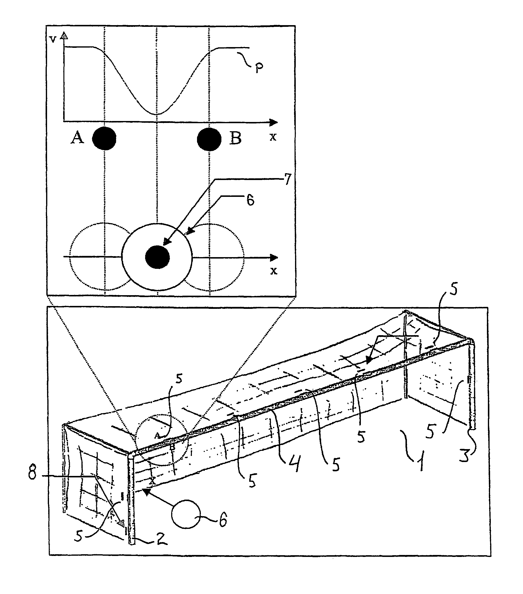
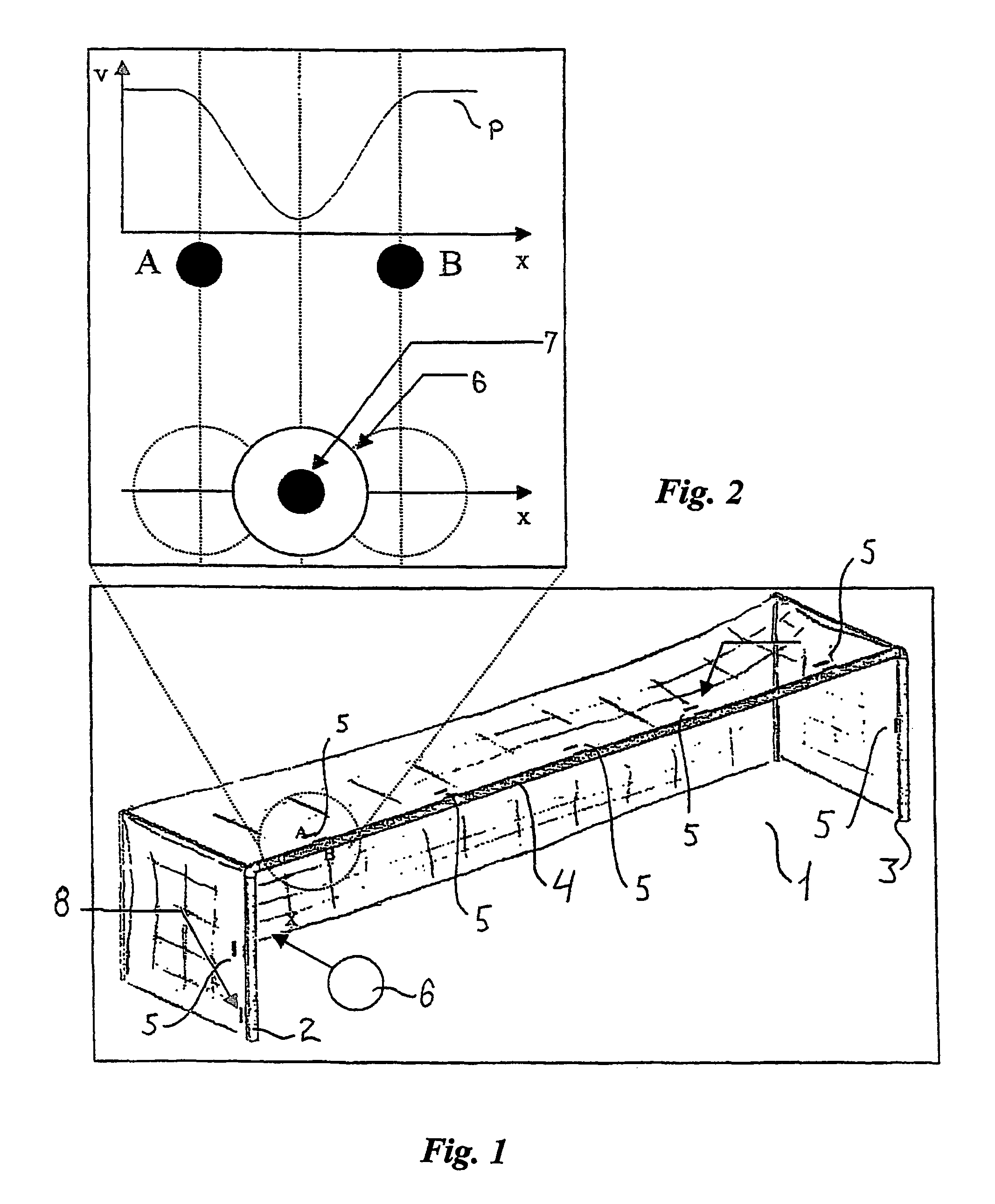
[0032]A football goal 1 is shown in FIG. 1 having a left goalpost 2, a right goalpost 3 and a horizontal crossbar 4 there between. The goal 1 is placed on a sports field with the posts 2, 3 placed on the centre of the goal line (not shown) and the crossbar 4 being parallel with and directly above the goal line in accordance with the laws of FIFA, so that the goal line, the posts 2, 3 and the cross bar 4 delimits a flat target plane.

[0033]Five pairs of antennas 5 are arranged equidistantly on the crossbar 4 and two pairs 5 are arranged each on one post 2, 3. Each pair of antennas 5 comprises two identical antennas A, B that are arranged parallel with a displacement only in the direction perpendicular to the target plane. The antennas A, B are arranged so that the midway position is situated precisely half the diameter of the ball from the back edge of the goal line. A goal is scored when the whole of the ball pass over the goal line, between the goalposts 2, 3 and under the cross bar...


PUM


Abstract

A system is disclosed for detection of whether a movable object, such as a sports object, e.g. a football or an ice hockey puck, has passed a flat plane in space, such as a goal plane defined e.g. as a vertical plane extending from a goal line or a horizontal plane defined by the upper rim of the basketball basket. The system comprises a plurality of pairs of antennas arranged along the periphery of the flat target plane, the two antennas of each of said pairs being arranged with a mutual displacement in the direction perpendicularly to the flat target plane, radio wave emitter means arranged in the movable object and / or each antenna, and means for receiving the radio waves from the radio wave emitter means and provide an output accordingly arranged in each antenna and / or in the movable object, the system further comprising processing means to receive and process said output together with a predetermined set of conditions and providing a resulting output if the set of conditions are fulfilled so as to determine whether the movable object passes the flat target plane.

Description

TECHNICAL FIELD OF THE INVENTION[0001]The present invention relates to a system for detection of whether a movable object, such as a sports object, e.g. a football or an ice hockey puck, has passed a flat plane in space, such as a goal plane defined e.g. as a vertical plane extending from a goal line or a horizontal plane defined by the upper rim of the basketball basket.BACKGROUND[0002]Traditionally, the referee or referees of a sports match decides from visual observation whether or not the ball has passed the goal plane. However, this may be very difficult to determine correctly in situations where the ball is returned quickly and has only just passed, or not passed, the goal plane, and it is particularly difficult if the referee is positioned unsuitably with respect to the goal plane or is engaged in other activity of the match. Video camera may also be used to monitor the goal planes, but the spatial and temporal resolution of video cameras are often not sufficient to provide t...

Claims


Application Information

Patent Timeline
Patent Type & Authority Patents(United States)
IPC IPC(8): A63B63/00A63B43/00A63B71/06
CPCA63B24/0021A63B63/004A63B71/0605A63B43/00A63B63/00A63B2024/0037A63B2071/0611A63B2220/83A63B2220/89A63B2225/50A63B2243/0025A63B2243/0045A63B2102/24A63B71/06
Inventor PETERSEN, HANS
Owner FRAUNHOFER GESELLSCHAFT ZUR FOERDERUNG DER ANGEWANDTEN FORSCHUNG EV
Why Eureka
Try Eureka