
Image forming optical system and electronic image pickup apparatus using the same

an optical system and optical pickup technology, applied in optics, instruments, lenses, etc., can solve the problems of chromatic aberration, chromatic aberration generation, and the tendency to reduce the imaging performan

Inactive Publication Date: 2011-01-11
OLYMPUS CORP
View PDF5 Cites 7 Cited by
  • Summary
  • Abstract
  • Description
  • Claims
  • Application Information

AI Technical Summary

Benefits of technology

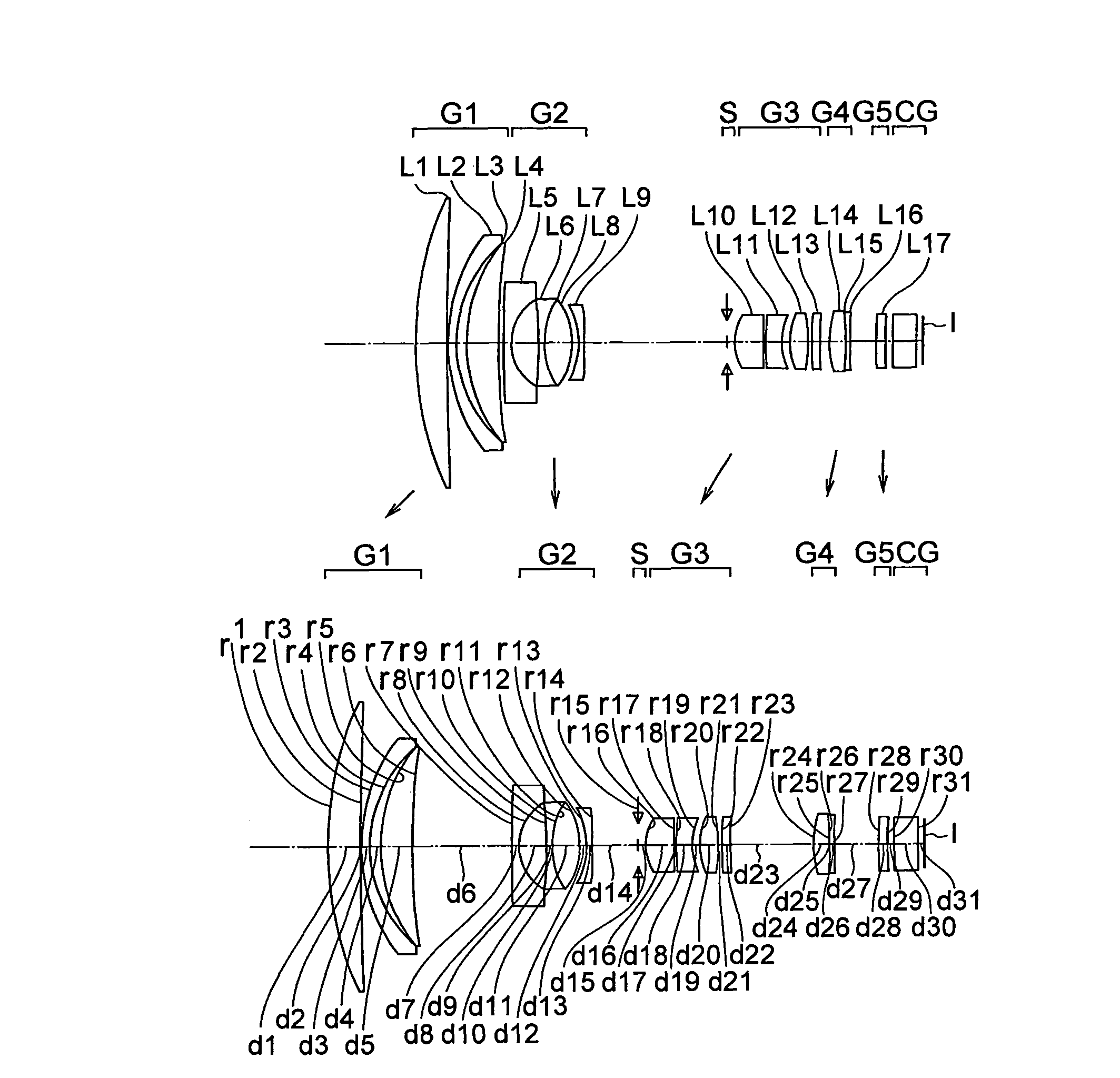
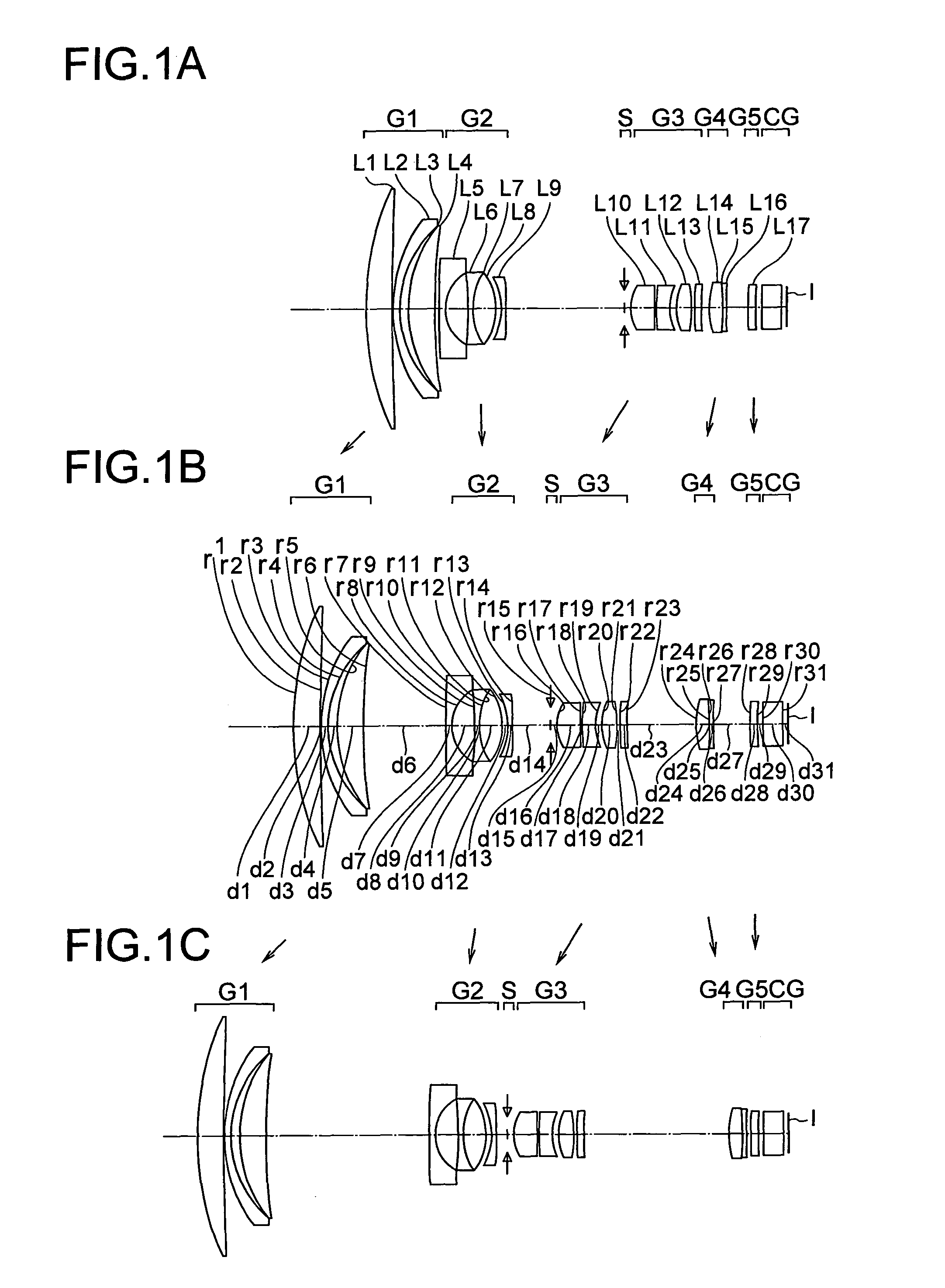
The present invention provides an image forming optical system and an image pickup apparatus that use a cemented optical element and a refractive optical element to achieve a desired optical effect during zooming. The system includes a first lens group, a second lens group, and an image side lens group, with the distance between the first lens group and the second lens group changing during zooming. The refractive optical element has a positive refracting power and is made up of an optical element disposed on the object side and a refractive optical element disposed on the image side. The system satisfies certain conditional expressions to achieve the desired optical effect. The technical effect of the invention is to provide an image forming optical system and an image pickup apparatus that can change the optical configuration during zooming to achieve the desired optical effect.

Problems solved by technology

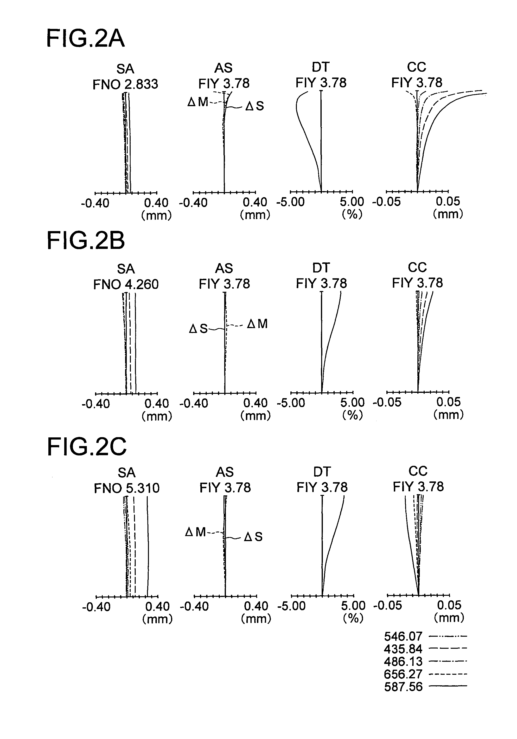
However, the shorter the entire lens length is made in order to reduce the size of the entire optical system, the more aberrations, in particular chromatic aberrations, tend to be generated, and the lower the imaging performance tends to become.

Method used


Image

  • Image forming optical system and electronic image pickup apparatus using the same
  • Image forming optical system and electronic image pickup apparatus using the same
  • Image forming optical system and electronic image pickup apparatus using the same

Examples


example 1

[0304]

unit mmSurface dataSurface no.rdndνdeffective radiusObject plane∞∞ 160.9825.351.6485053.0224.00 2495.7440.1923.38 331.1721.281.9228618.9017.70 422.2271.771.6338723.3816.35 526.8775.231.4970081.5416.31 6101.913Variable16.00 7303.8141.101.8830040.769.68 88.3124.796.82 9−46.2540.801.8830040.766.711012.3960.011.5140042.836.691112.3964.871.7847225.686.6912−12.6841.156.7213−11.4990.801.7725049.605.7214*−230.432Variable5.7215 (stop)∞1.303.3916*10.7434.931.5891361.143.9617−78.0510.104.061828.0412.771.8466623.784.071910.2951.423.872012.8263.121.4970081.544.2121−36.9850.644.2922*39.2071.361.5307155.694.2923*33.196Variable4.282419.1302.681.4970081.544.6025−119.0900.011.5140042.834.4726−119.0900.821.8040046.574.472776.031Variable4.4128*147.3741.631.5307155.694.1729*−67.9391.094.0930∞4.001.5168064.204.0231∞1.053.85Image plane∞Aspherical surface data14th surfaceK = 0.000, A2 = 0.0000E+00, A4 = −7.99095e−05, A6 = −9.37486e−07,A8 = 4.32991e−08, A10 = −1.00218e−0916th surfaceK = 0.000, A2 = 0....

example 2

[0305]

unit mmSurface dataSurface no.rdndνdeffective radiusObject plane∞∞ 159.9634.201.4970081.5418.60 22486.1420.1017.76 341.7000.991.8466623.7815.50 425.3670.721.6338723.3814.76 528.6404.191.6779055.3414.74 6111.334Variable14.50 7110.4221.101.8830040.769.11 88.0834.796.49 9−46.2540.801.8830040.766.241012.3960.011.5140042.836.101112.3964.871.7847225.686.1112−12.6841.156.0713−11.4990.801.7725049.605.0814*−125.405Variable5.0015 (stop)∞1.303.4816*10.7434.931.5891361.144.0717−78.0510.104.161828.0412.771.8466623.784.161910.4691.423.942013.6113.121.4970081.544.2521−36.9850.644.3322*63.8681.361.5307155.694.3323*48.855Variable4.342419.1302.681.4970081.544.6525−119.0900.011.5140042.834.5126−119.0900.821.8040046.574.512776.031Variable4.4628*147.3741.631.5307155.694.2129*−67.9391.094.1830∞4.001.5168064.204.0931∞1.053.86Image plane∞Aspherical surface data14th surfaceK = 0.000, A2 = 0.0000E+00, A4 = −8.14579e−05, A6 = −1.15665e−06,A8 = 6.76342e−08, A10 = −1.49231e−0916th surfaceK = 0.000, A2 = 0...

example 3

[0306]

unit mmSurface dataSurface no.rdndνdeffective radiusObject plane∞∞ 160.5783.831.4970081.5418.70 21959.8630.1018.64 344.6001.011.8211424.0615.50 424.5340.781.6700020.0014.71 527.7674.491.6935053.2114.69 6126.235Variable14.45 7139.9911.101.8830040.769.75 88.4674.796.96 9−46.2540.801.8830040.766.871012.3960.011.5140042.836.851112.3964.871.7847225.686.8612−12.6841.156.8813−11.4990.801.7725049.605.8014*−133.624Variable5.7915 (stop)∞1.303.4816*10.7434.931.5891361.144.0317−78.0510.104.091828.0412.771.8466623.784.081910.4941.423.852013.5843.121.4970081.544.1321−36.9850.644.1922*90.1591.361.5307155.694.1823*47.692Variable4.192419.1302.681.4970081.544.6525−119.0900.011.5140042.834.5226−119.0900.821.8040046.574.522776.031Variable4.4728*147.3741.631.5307155.694.2029*−67.9391.094.2230∞4.001.5168064.204.1131∞0.973.87Image plane∞Aspherical surface data14th surfaceK = 0.000, A2 = 0.0000E+00, A4 = −7.27292e−05, A6 = −1.76848e−06,A8 = 1.00411e−07, A10 = −1.83590e−0916th surfaceK = 0.000, A2 = 0...


PUM


Abstract

In a zoom lens, in which the distance between the first lens group and the second lens group changes during zooming, wherein a refractive optical element A that has a positive refracting power if its object side surface and its image side surface are interfaces with air is provided between an object side base optical element B and an image side base optical element C to constitute therewith a three-piece cemented optical element D in the first lens group, there is at least one optical element having a positive refracting power disposed closer to the object side than the three-piece cemented optical element D, and the zoom lens satisfies a certain condition.

Description

CROSS-REFERENCE TO RELATED APPLICATION[0001]The present application is based upon and claims the benefit of priority from the prior Japanese Patent Application No. 2009-39521 filed on Feb. 23, 2009; the entire contents of which are incorporated herein by reference.BACKGROUND OF THE INVENTION[0002]1. Field of the Invention[0003]The present invention relates to an image forming optical system and an electronic image pickup apparatus equipped with the same.[0004]2. Description of the Related Art[0005]In recent years, image pickup apparatuses such as digital cameras have been replacing silver salt films and becoming widely used. Digital cameras are adapted to pickup an image of an object using a solid state image pickup element such as a CCD or CMOS. Taking lenses used in such image pickup apparatuses are desired to be zoom lenses (image forming lenses) having high zoom ratios.[0006]It is desired that such image pickup lenses be satisfactorily corrected in terms of aberrations relevant ...

Claims


Application Information

Patent Timeline
Patent Type & Authority Patents(United States)
IPC IPC(8): G02B15/14
CPCG02B15/173G02B15/145129
Inventor NAKAGAWA, AKITAKAGOTO, HISASHI
Owner OLYMPUS CORP
Learn More