
Radio repeater for mobile communication system and repeating method using the same

a mobile communication system and radio frequency repeater technology, applied in the field of apparatus and methods of radio frequency repeaters, can solve the problems of increasing installation costs, oscillation problems, and performance degradation of repeaters, and achieve the effect of continuously operating the system

Active Publication Date: 2011-01-11
SK TELECOM CO LTD
View PDF12 Cites 2 Cited by
  • Summary
  • Abstract
  • Description
  • Claims
  • Application Information

AI Technical Summary

Benefits of technology

The present invention provides an apparatus and method of a radio repeater that can simultaneously analyze channel characteristics in parallel and eliminate feedback signals so as to adapt to various multi-path environment conditions surrounding antennas and perform operation adaptively to propagation environments, ensuring system stability function not to affect services upon detection of oscillation phenomenon, thereby improving the stability and reliability of a repeater and service quality. The invention also provides an apparatus and method that controls transmission time so as to avoid superposition of feedback signals and multi-path signals, process many multi-path channel signals, and eliminate undesired noise signals. The invention further provides an apparatus and method that automatically adjusts optimal gain value and phase and magnitude of feedback signals using a predetermined target output magnitude value inputted from the control unit.

Problems solved by technology

However, in the radio frequency repeater, transmitting and receiving antennas are located at adjacent distance each other, so those transmission signals from a transmitting antenna are fed back to a receiving antenna, thereby causing the performance degradation of the repeater.
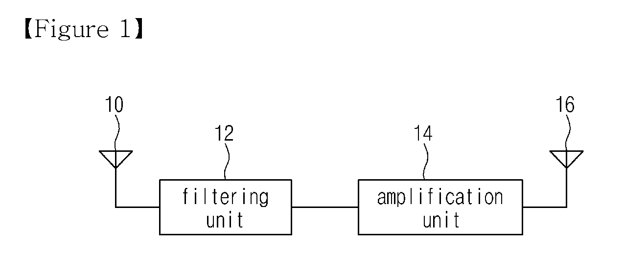
In the radio frequency repeater illustrated in FIG. 1, there is a problem in that, if signals output from the second antenna 16 is strong, the transmitted signals from antenna 16 are fed back to the first antenna 10, and then amplified and are transmitted through the second antenna 16 again, thereby causing an oscillation problem.
In order to avoid such oscillation phenomenon, the transmitting and receiving antennas, 10 and 16, must be placed far a part each other such that the extent of isolation between the first antenna 10 and the second antenna 16 is higher than an amplification gain, thereby there being a disadvantage in that increasing the installation cost.
Furthermore, there exist constraints in which the amplification gain of a radio frequency repeater should be designed to have a decreased value in order to minimize the side effects of the aforementioned feedback phenomenon.
Generally, the analog processing method is implemented by compensating the amplitude, phase, delay, or the like of signals using dedicated hardware, so that, for the degree of flexibility is low, high cost is required and accuracy is degraded.
The above Korean Patent No. 03422002, disclosing an analog processing method which processes radio frequency signals systematically, has disadvantage in that there is limitation in adapting to noise or distortion occurring in various operational environments surrounding antennas, and the efficiency of elimination of multi-path feedback interference signal decreases because multi-path channels can not be simultaneously processed.
So aforementioned patent have disadvantage in that normal operation service should be terminated and it switches to initial mode to adapt changing environment when oscillation occurs in the normal operation mode.
These phenomena degrade the service of quality even more can not service during estimation mode.
So it provide multi stage inverse-phased combiner in order to reflect various operation environments, but a fixed number of multi-stage combiners implemented by hardware have limitation to accommodate various propagation environments which continuously vary.

Method used


Image

  • Radio repeater for mobile communication system and repeating method using the same
  • Radio repeater for mobile communication system and repeating method using the same
  • Radio repeater for mobile communication system and repeating method using the same

Examples


Embodiment Construction

[0053]Reference now should be made to the drawings, in which the same reference numerals are used throughout the different drawings to designate the same or similar components.

[0054]FIG. 3 is a diagram illustrating the construction of a radio repeater according to the present invention.

[0055]As illustrated in FIG. 3, the radio repeater according to the present invention includes a receiving antenna 32 for receiving signals to be repeated, a band-pass filtering unit 34 for filtering out noise components from signals received from the receiving antenna, an adaptive feedback estimator and eliminator 30 for eliminating feedback signals from signals output from the filtering unit 34 and controlling and outputting a gain, an amplification unit 36 for amplifying signals output from the adaptive feedback estimator and eliminator 30, and a transmitting antenna 38 for outputting the signals amplified by the amplification unit 36.

[0056]In this case, the adaptive feedback estimator and eliminat...


PUM


Abstract

Disclosed herein is a radio frequency (RF) repeater comprising an analog signal processing unit and a digital signal processing unit, wherein the analog signal processing unit includes a filtering unit; an amplification unit on receiving side; a frequency conversion unit on receiving side; a frequency conversion unit on transmitting side; and an amplification unit on transmitting side, and the digital signal processing unit includes a receiving signal detection unit; the automatic gain control unit; a feedback signal detection unit; a feedback signal combining unit; a feedback signal elimination unit; an automatic delay control unit; and the control unit.According to the RF repeater and repeating method, installation cost is reduced, limitations in output magnitude and installation are overcome, and ensuring high output power characteristics.

Description

CROSS REFERENCE TO RELATED APPLICATION[0001]This application is the National Phase application of International Application No. PCT / KR2006 / 005596, filed Dec. 20, 2006, which designates the United States and was published in English. This application, in its entirety, is incorporated herein by reference.TECHNICAL FIELD[0002]The present invention relates to an apparatus and method of a radio frequency (RF) repeater in use for the improvement of quality of service in mobile communication systems. In particular, this RF repeater estimates feedback interference signals which are transmitted from a transmitting antenna and fed back to a co-located receiving antenna, and eliminates these feedback signals, and, thus can improve the quality of service by avoiding the oscillation.BACKGROUND ART[0003]Generally, a RF repeater extends the cell coverage which provides mobile communication services at low cost even in shadow areas, such as the inside of a building or underground, and that is used ...

Claims


Application Information

Patent Timeline
Patent Type & Authority Patents(United States)
IPC IPC(8): H04B7/14
CPCH04B7/15578
Inventor PARK, SUNG-YOULCHO, SUNG-MINCHOI, GYEONG-HOLEE, BYUNG-SUKIHM, JONG-TAELEE, JOO-SIKBAIK, SUNG-JUNKIM, SEONG-KEUN
Owner SK TELECOM CO LTD
Learn More