Forming limit strain analysis

a strain analysis and forming technology, applied in the direction of cad techniques, tensile/compressive force-using materials, instruments, etc., can solve the problems of low stress sensitivity, comparability and intuitive assessment of strain states lost in this manner, and non-proportional strain paths occur in real forming processes, so as to improve the ability to interpret and represent the effect of reducing the difficulty

Active Publication Date: 2011-01-18
NETABTAL MASCHEN
View PDF3 Cites 8 Cited by
  • Summary
  • Abstract
  • Description
  • Claims
  • Application Information

AI Technical Summary

Benefits of technology

[0015]It is therefore the object of the invention to provide a method for the forming limit strain analysis of the initially mentioned type, which permits an improved analysis, assessment and visualisation of forming limit strain states, as well as a corresponding computer program, a data carrier and a data processing device.
[0018]Thus, only a single forming limit strain curve is required, and all observed points (equivalent strain states) in the strain space may be assessed with respect to the same curve. Even with non-proportional trajectories, a uniform analysis and also a comparison of different states of the material may be effected by way of this. The representation is simplified and the technical information and interpretation ability is significantly improved.

Problems solved by technology

However, non-proportional strain paths occur in real forming processes.
Evidently, the comparability and the intuitive assessment of strain states are lost in this manner.
In practice, there exists the problem that the failure assessment with such stress curves is not familiar to the users of respective simulation programs, and that the sensitivity of the stresses is very low in the region of the forming limit stress curve, i.e. also larger strain changes lead to only small stress changes as a result of the slight material hardening in the vicinity of the failure, so that even small uncertainties in the position of a stress state to be assessed, may make the difference between failure and non-failure.
However, no back-transformation for determining equivalent strains from the stresses is disclosed.
However, no back-transformation for determining equivalent strains from stresses is disclosed.
However, here too, no back-transformation for determining equivalent strains for stresses is disclosed.

Method used


Image

  • Forming limit strain analysis
  • Forming limit strain analysis
  • Forming limit strain analysis

Examples


Embodiment Construction

[0041]In each case, in a material point, a given material state with respect to its strains is represented by an equivalent strain state, wherein the equivalent strain state is produced by a proportional strain trajectory, which leads to the same stress state which the given material state has. The given material state is hereinafter called “target state”, since the desired proportional strain trajectory is indeed to lead to this state.

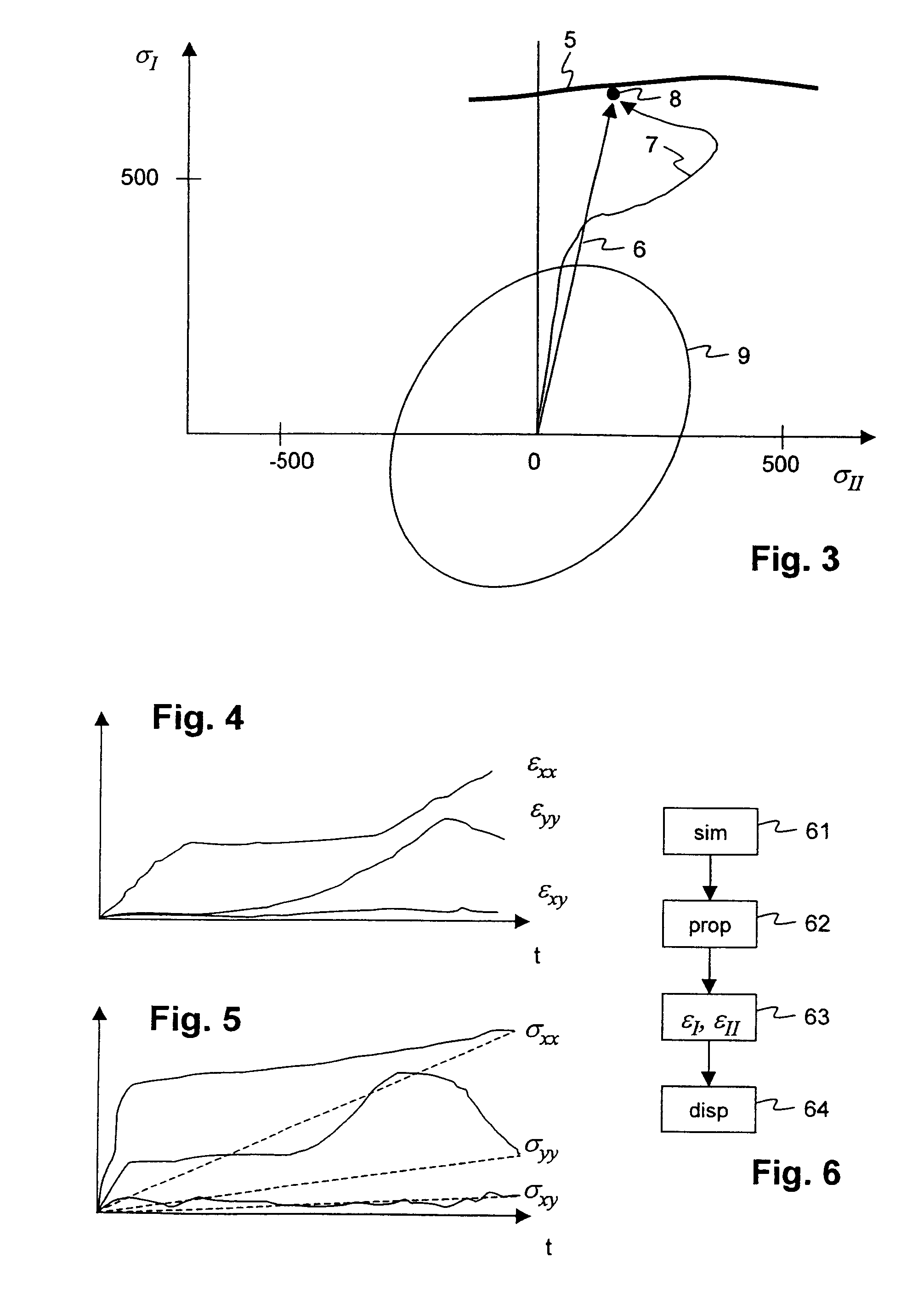
[0042]The stresses in the target state are represented for example by way of a plane stress state or a plane stress tensor [σxx, σyy, σxy]. By way of a main axis transformation, the stress state [σxx, σyy, σxy] in the known manner is represented by a major stress and a minor stress σI, σII, and may be represented by a point 8 in the stress plane, as in FIG. 3. The stresses are determined by way of FEM-simulation of the forming operation to be examined. The generally known yield surface (or yield locus) 9 is also drawn in the stress plane. FIG. 5 shows...


PUM

PropertyMeasurementUnit
equivalent plastic strains εijpaaaaaaaaaa
equivalent plastic strainaaaaaaaaaa
plastic multiplieraaaaaaaaaa

Abstract

In the computed-based analysis of forming processes, for example, manufacturing sheet metal parts for the automobile industry, the material loading is represented by major and minor strains εI, εII and is visualised with respect to a forming limit strain curve. In the method according to the invention, one proceeds from a target state (4n) of the material, as has been determined in the computed simulation of the forming process. A proportional trajectory of a loading and thus of the state variables of the material, in particular of the stresses (σ), is determined, which leads to the same target state. The associated proportional strain trajectory is evaluated for this proportional loading trajectory. The strain state (4p) which results from this strain trajectory, is called the equivalent strain state (4p) and may be used in the forming limit strain diagram for assessing the target state. Thereby, the equivalent strain state is set in relation to the forming limit strain curve (1) for the proportional trajectories.

Description

BACKGROUND OF THE INVENTION[0001]The invention relates to the field of numerical analysis of forming processes, as occur when machining sheet metal by way of forming technology. It particularly relates to a method for forming limit strain analysis, and to a corresponding computer program, to a data carrier, and to a data processing device, according to the preamble of the respective independent claims.DESCRIPTION OF THE STATE OF THE ART[0002]Forming parts, in particular sheet metal forming parts for the manufacture of automobiles for example, as a rule, are manufactured by way of deep-drawing. Semi-finished products, so-called sheet metal billets, are placed in multi-part forming tools for this purpose. The parts are formed by way of presses, in which the forming tools are clamped. As a rule, the parts are manufactured from a flat sheet metal billet via several forming stages, such as drawing, finish bottoming, adjustment, etc., combined with cutting steps.[0003]CAD / CAE programs (co...

Claims


Application Information

Patent Timeline
Patent Type & Authority Patents(United States)
IPC IPC(8): G01N3/08
CPCG06F17/5009G06F17/5095G06F2217/16G06F2217/42G06F30/15G06F30/20G06F2111/10G06F2113/24
Inventor KUBLI, WALDEMARSESTER, MATTHIAS
Owner NETABTAL MASCHEN
Why Eureka
Try Eureka