Continuous alignment system for fire control

a technology of continuous alignment and fire control, applied in the direction of weapons, aiming means, weapon components, etc., can solve the problems of increased complexity, increased complexity, and increased complexity, and achieve the effect of increasing the chance of error, increasing complexity, and increasing complexity

Inactive Publication Date: 2011-01-18
LOCKHEED MARTIN CORP
View PDF11 Cites 37 Cited by
  • Summary
  • Abstract
  • Description
  • Claims
  • Application Information

AI Technical Summary

Problems solved by technology

Fire control systems have evolved much higher complexity along with the weapon systems with which they are associated.
In large part, this increase in complexity has arisen from increased automation permitted by rapid growth in powerful computing technology.
Increased complexity typically affords increased opportunity for error.
These can arise from such various sources incorrectly reckoning the position to which a moving target will move, errors in data entry, and differences in reference systems between different sources of positioning information.
Weight reduction efforts and integration complexities have forced separation of the gun targeting system from the gun turret so that the gun and targeting system experience a different set of alignment errors.
Unknown alignment errors between the MR EO / IR sensor and the gun coordinate systems could cause errors in target position and velocity when referenced to the gun coordinate system during firing.
The ARV-A (L), as a 2½ ton to 3 ton class system, will not have the massive and rigid structure traditionally associated with combat vehicles, which will make retention of bore sight alignment much more difficult.
Effects of shock and vibration, solar heating, reduced vehicle stiffness through use of light weight materials, and the need to constantly travel over rough terrain will increase the need for bore sighting.
On an unmanned vehicle, this is very undesirable, as traditional bore sighting requires at least one man to be involved.
A kingpost design further complicates alignment of the sensor to the weapon systems, as two distinct points of azimuth and elevation rotation will exist-one for the sensor, and one for the weapons.
This process would eliminate most alignment error between the two azimuth planes, but would not be a complete solution.

Method used


Image

  • Continuous alignment system for fire control
  • Continuous alignment system for fire control
  • Continuous alignment system for fire control

Examples


Embodiment Construction

[0030]Illustrative embodiments of the invention are described below. In the interest of clarity, not all features of an actual implementation are described in this specification. It will of course be appreciated that in the development of any such actual embodiment, numerous implementation-specific decisions must be made to achieve the developers' specific goals, such as compliance with system-related and business-related constraints, which will vary from one implementation to another. Moreover, it will be appreciated that such a development effort, even if complex and time-consuming, would be a routine undertaking for those of ordinary skill in the art having the benefit of this disclosure.

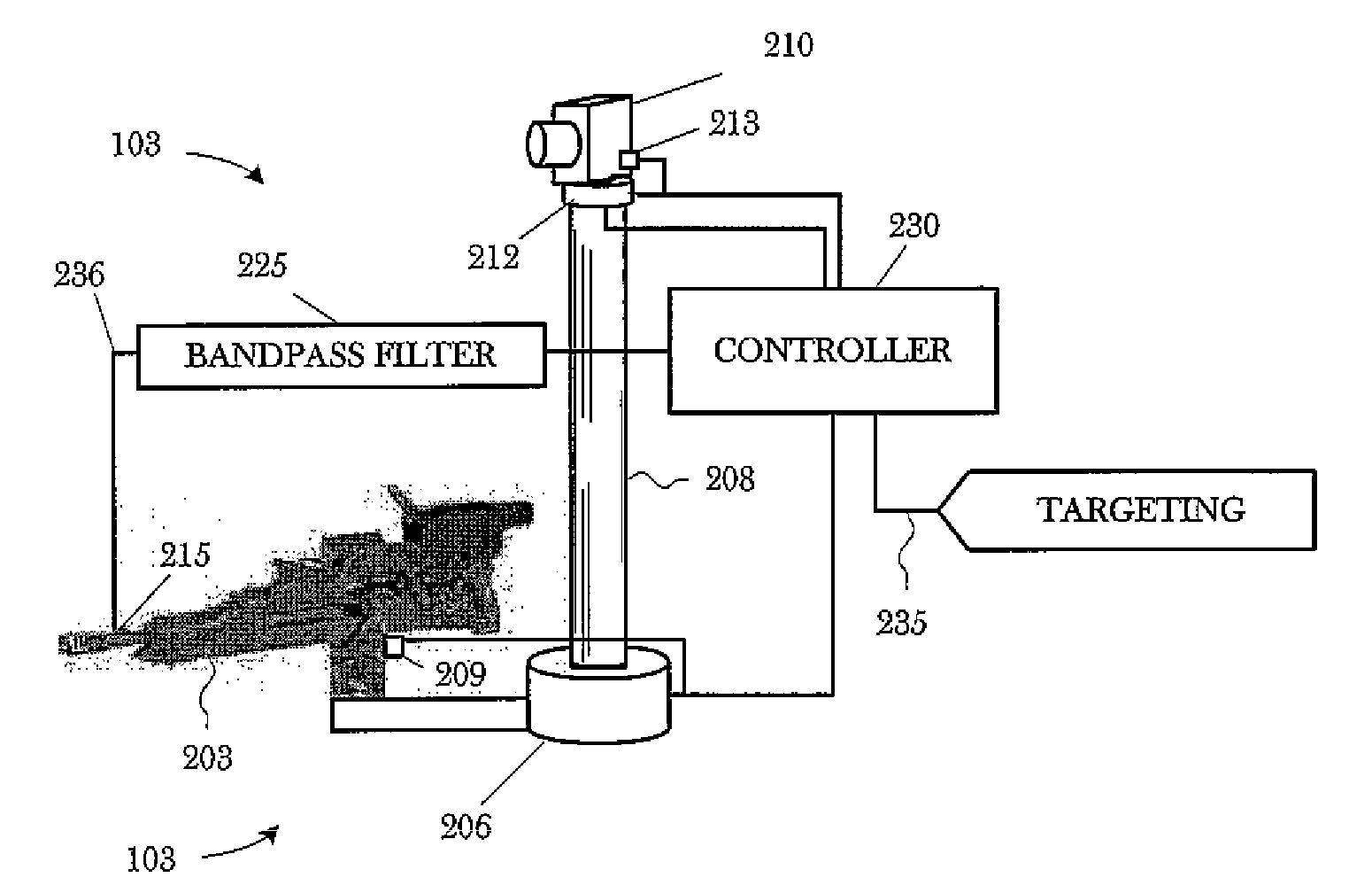
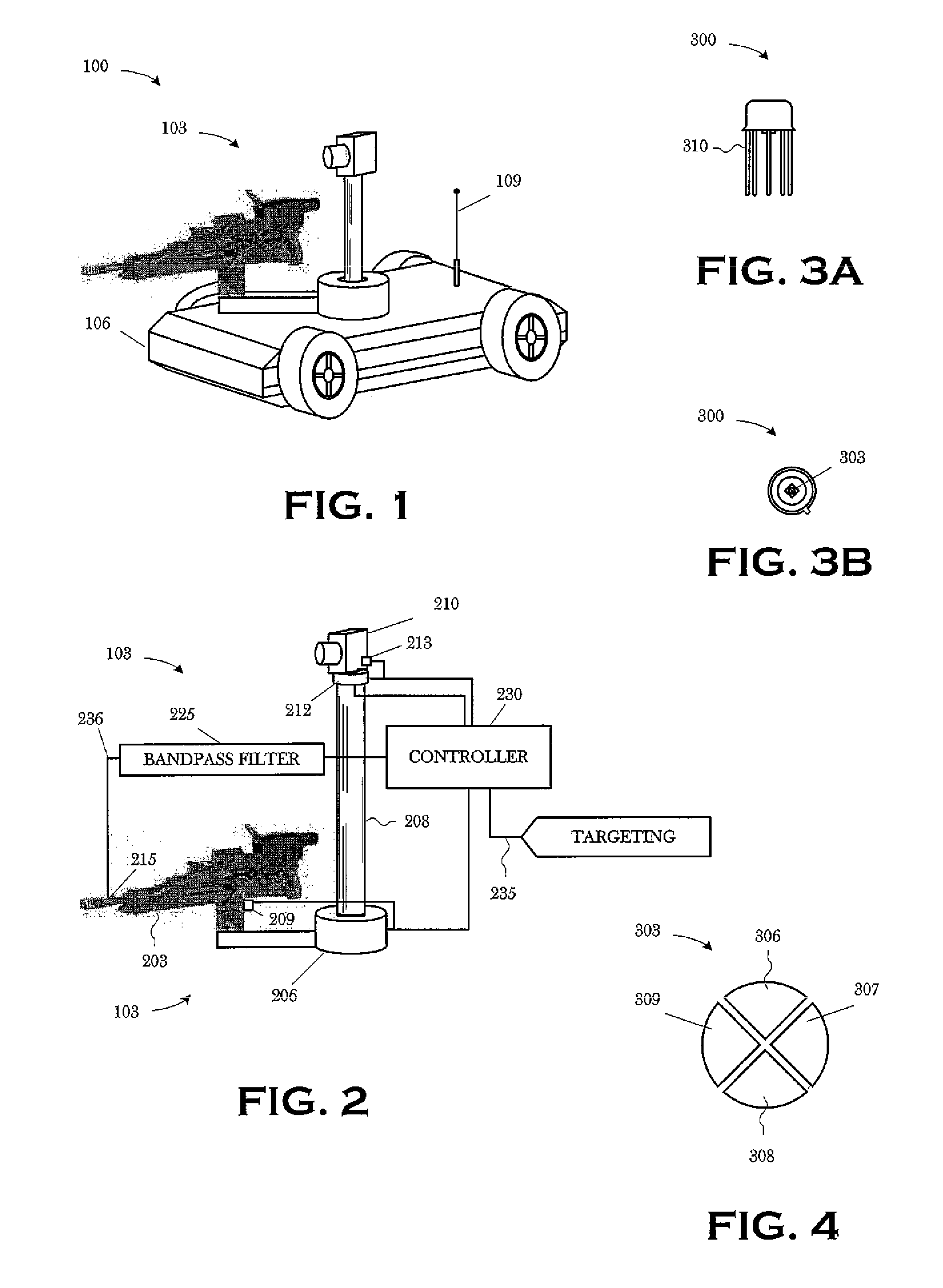
[0031]FIG. 1 is a perspective view of an apparatus 100 including a weapon system 103 constructed and operated in accordance with the present invention. The weapon system 103 is mounted to a vehicle 106. In the illustrated embodiment, the vehicle 106 is robotic or autonomous, i.e., there is no hum...


PUM


Abstract

In a first aspect, an automated method for engaging a target comprises: slewing a weapon to an estimated target state; and aligning the weapon's boresight with the actual target state. Aligning the weapon's boresight with the actual target state includes designating the target to obtain the actual target state; and zeroing an offset between the actual target state and the estimated target state. In a second aspect, an apparatus, comprises: means for slewing a weapon to an estimated target state; and means aligning the weapon's boresight with the actual target state. The aligning means includes designating the target to obtain the actual target state; and zeroing an offset between the actual target state and the estimated target state. In a third aspect, a weapon system comprises: a targeting sensor capable of designating a target; a weapon; and an alignment sensor associated with the weapon, and capable of receiving the designation and aligning the weapon's boresight with the designated target. In a fourth aspect, a laser rangefinder, comprises: a laser designator capable of designating a target from an estimated target state; and a quad cell detector capable of receiving the designation.

Description

[0001]This is a continuation of U.S. application Ser. No. 11 / 675,419 (“the '419 application”), entitled “Continuous Alignment System for Fire Control”, filed Feb. 15, 2007 now abandoned, in the name of the inventors Michael R. Willingham and Robert J. McCarty, Jr. The '419 application claimed the earlier effective filing date of U.S. Provisional Application Ser. No. 60 / 773,531 (“the '531 application”), entitled “CONTINUOUS ALIGNMENT SYSTEM FOR FIRE CONTROL” filed Feb. 15, 2006, in the name of the inventors Michael R. Willingham and Robert J. McCarty, Jr. The earlier effective filing dates of the '419 and '531 applications are hereby claimed for all common subject matter. The '419 and '531 applications are also hereby incorporated by reference in its entirety for all purposes as if expressly set forth verbatim herein.[0002]The U.S. Government has a paid-up license in this invention and the right in limited circumstances to require the patent owner to license others on reasonable term...

Claims


Application Information

Patent Timeline
Patent Type & Authority Patents(United States)
IPC IPC(8): F41G3/14
CPCF41G3/06F41G3/145F41G3/165F41G5/18
Inventor WILLINGHAM, MICHAEL R.MCCARTY, JR., ROBERT J.
Owner LOCKHEED MARTIN CORP
Why Eureka
Try Eureka