
Air-cushion type shock absorbing system that is operated in a wireless controlling manner

Active Publication Date: 2011-01-18
PIN HSIU TECH
View PDF13 Cites 11 Cited by
  • Summary
  • Abstract
  • Description
  • Claims
  • Application Information

AI Technical Summary

Benefits of technology

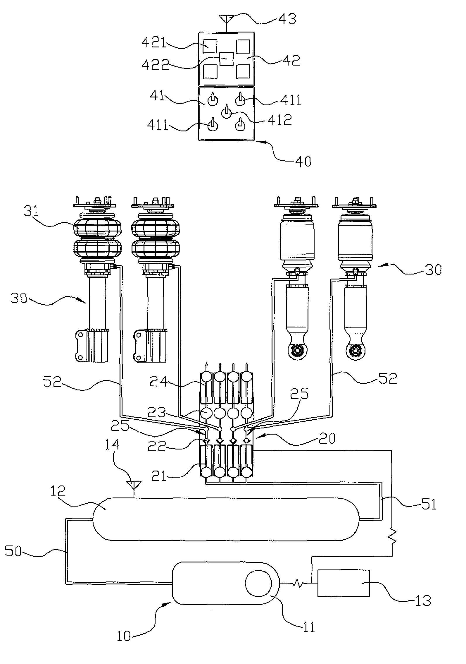
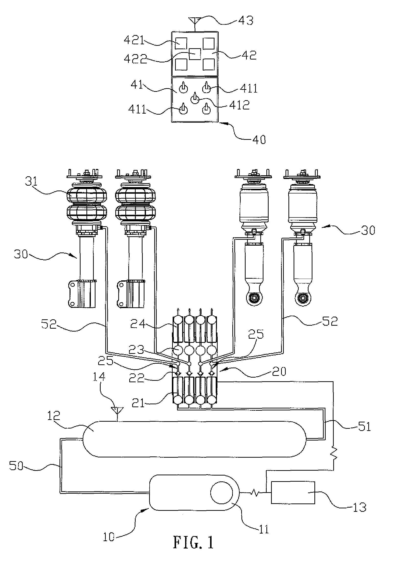
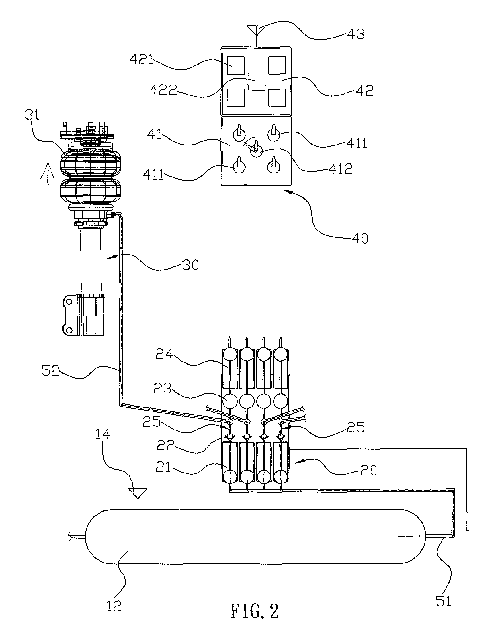
[0009]A further objective of the present invention is to provide a shock absorbing system, wherein each of the shock absorbers can be lifted to lift the chassis of the car so as to prevent the chassis of the car from being worn out or broken due to a violent hit when the car passes a rugged road and can be lowered to lower the chassis of the car so as to enhance maneuverability of the car.
[0010]A further objective of the present invention is to provide a shock absorbing system, wherein movement of each of the shock absorbers is controlled by a wireless signal transmission without having to provide any signal line, thereby facilitating assembly of the shock absorbing system.
[0011]A further objective of the present invention is to provide a shock absorbing system, wherein the shock absorbers can be controlled individually by the first switches of the drive unit and can be controlled simultaneously by the second switch of the drive unit, thereby facilitating the driver operating the shock absorbing system.
[0012]A further objective of the present invention is to provide a shock absorbing system, wherein the second indication light of the drive unit can indicate the lifting condition of each of the shock absorbers by provision of the wireless pressure detector of the air container and can indicate the lowering condition of each of the shock absorbers by provision of the wireless pressure detector of each of the control units, so that the drive can understand the lifting and lowering conditions of the chassis of the car so as to enhance the driving safety.

Problems solved by technology

However, the shock absorbing system cannot be micro-adjusted easily and quickly.

Method used


Image

  • Air-cushion type shock absorbing system that is operated in a wireless controlling manner
  • Air-cushion type shock absorbing system that is operated in a wireless controlling manner
  • Air-cushion type shock absorbing system that is operated in a wireless controlling manner

Examples


Embodiment Construction

[0017]Referring to the drawings and initially to FIG. 1, a shock absorbing system in accordance with the preferred embodiment of the present invention is mounted on a wheeled vehicle, such as an automobile and the like, and comprises an air container 12, a power source 10 connected to the air container 12 to supply a high-pressure air into the air container 12, a plurality of shock absorbers 30 each provided with at least one air spring 31, a central controller 20 connected between the air container 12 and the shock absorbers 30 and including a plurality of control units 25 each connected between the air container 12 and a respective one of the shock absorbers 30 to transmit the high-pressure air in the air container 12 into the respective shock absorber 30 so as to inflate the air spring 31 of the respective shock absorber 30 or to drain the high-pressure air outwardly from the respective shock absorber 30 so as to deflate the air spring 31 of the respective shock absorber 30, and ...


PUM


Abstract

A shock absorbing system includes an air container, a power source to supply a high-pressure air into the air container, a plurality of shock absorbers each provided with at least one air spring, a central controller including a plurality of control units each connected between the air container and a respective one of the shock absorbers, and a drive unit to control operation of the central controller in a wireless way. Thus, each of the shock absorbers can be lifted to lift the chassis of the car so as to prevent the chassis from being worn out or broken due to a violent hit when the car passes a rugged road and can be lowered to lower the chassis of the car so as to enhance maneuverability of the car.

Description

BACKGROUND OF THE INVENTION[0001]1. Field of the Invention[0002]The present invention relates to a shock absorbing system and, more particularly, to an air-cushion type shock absorbing system for a wheeled vehicle, such as an automobile and the like.[0003]2. Description of the Related Art[0004]A conventional shock absorbing system for a car is mounted on the chassis of the car to provide a shock-absorbing effect to the user. The shock absorbing system can be micro-adjusted to lift the chassis of the car so as to prevent the chassis of the car from being worn out or broken due to a violent hit when the car passes a rugged road. Alternatively, the shock absorbing system can also be micro-adjusted to lower the chassis of the car so as to enhance maneuverability of the car. However, the shock absorbing system cannot be micro-adjusted easily and quickly.[0005]The closest prior art references of which the applicant is aware were disclosed in U.S. Pat. Nos. 6,581,918 and 6,607,186.BRIEF SU...

Claims


Application Information

Patent Timeline
IPC IPC(8): B60G17/04
CPCB60G11/27B60G13/10B60G17/06B60G2600/202B60G2500/30
Inventor LIN, CHENG-HSIUNG
Owner PIN HSIU TECH
Learn More