Projection image display apparatus

a projection image and display device technology, applied in the field of projection image display devices, can solve the problems of significant deterioration of the resolution the trapezoidal distortion of the projected image, and the person making a presentation near the screen, so as to achieve the effect of shortening the distan

Active Publication Date: 2011-01-18
SANYO ELECTRIC CO LTD
View PDF14 Cites 8 Cited by
  • Summary
  • Abstract
  • Description
  • Claims
  • Application Information

AI Technical Summary

Benefits of technology

[0010]Accordingly, an object of the present invention is to allow smooth correction of a trapezoidal distortion by a small-sized reflecting mirror.
[0012]According to the present invention, since light is converged by the first mirror, light incident on the second mirror can be reduced in size, which leads to miniaturization of the second mirror. Accordingly, the mirror actuator for driving the second mirror can be made compact, thereby preventing the upsizing of the overall projector.
[0014]In the present invention, by disposing the second mirror such that the light path of the light reflected by the second mirror intersects with the light path of the light passing through the lens unit, it is possible to shorten a distance (a distance H in a direction of a Z axis in FIG. 11) between a projection image display apparatus and a projection plane (screen surface) as shown in FIG. 11, for example.

Problems solved by technology

This kind of projector may cause a trapezoidal distortion in a projected image due to a discrepancy between a direction of an optical axis of a projection lens and a direction of a normal line to a projection plane.
In addition, this kind of projector relieves a problem in that a person making a presentation near a screen suffers from the glare of light from the projector.
In this case, although the trapezoidal distortion may be corrected by signal processing as stated above, there will occur a problem in that a resolution of the projected image deteriorates significantly.
Further, in correcting the trapezoidal distortion by adjusting an installation state of the projector, only a slight change in the installation state greatly changes a position of a projected image, which causes a problem in that it is extremely difficult to let a projected image contained in a screen surface while correcting the trapezoidal distortion.
Moreover, in correcting the trapezoidal distortion by reflecting projection light by an angle-adjustable reflecting mirror, there will cause a problem in that the reflecting mirror needs to have a larger area as a tilting angle of projection light is increased with respect to the normal line to a screen plane, which leads to upsizing of the reflecting mirror.
In this case, upsizing the reflecting mirror would cause a drive actuator in the reflecting mirror to be larger in size, resulting in the upsizing of the overall projector.

Method used


Image

  • Projection image display apparatus
  • Projection image display apparatus
  • Projection image display apparatus

Examples


first embodiment

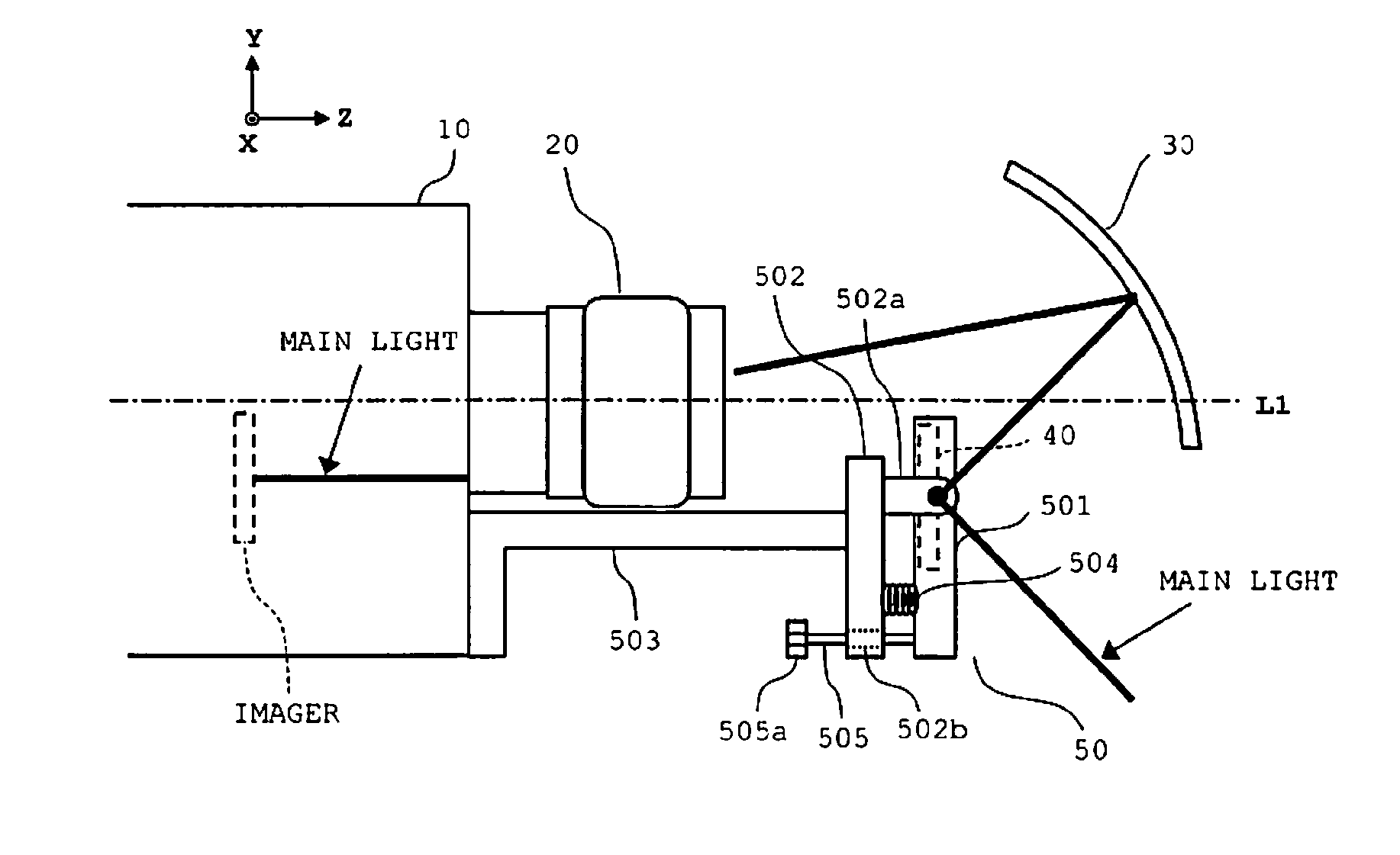
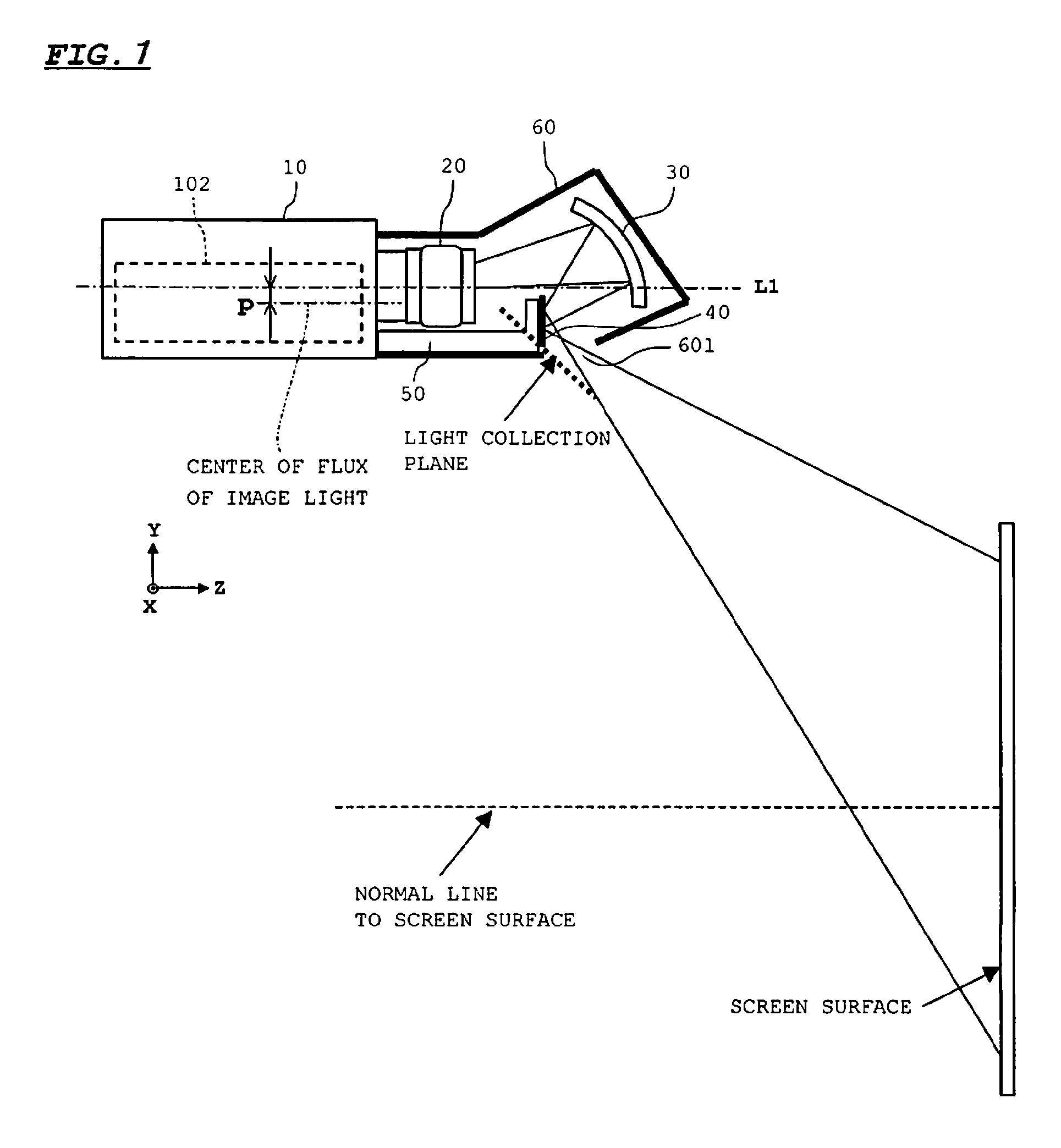
[0052]FIG. 1 is a diagram showing a configuration of a projector in a first embodiment. As shown in the diagram, the projector includes an enclosure 10, a lens unit 20, a first reflecting mirror 30, a second reflecting mirror 40, a mirror actuator 50, and a cover 60.

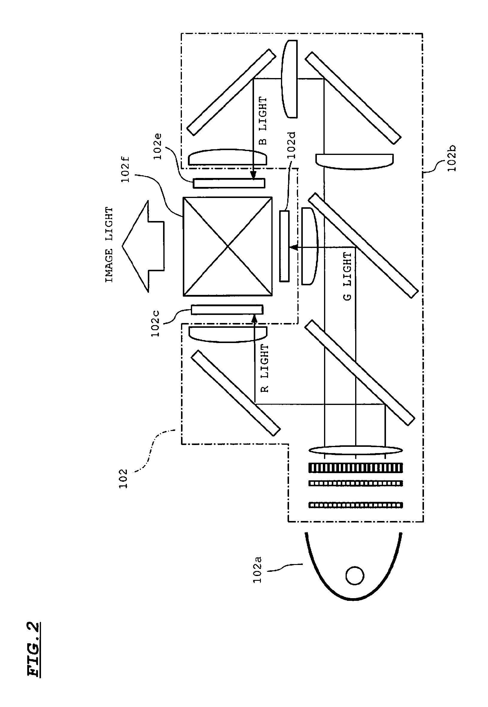
[0053]The enclosure 10 accommodates an optical engine 102 which generates image light modulated in accordance with an image signal. The generated image light is entered from the optical engine 102 into the lens unit 20. The image light here is entered into the lens unit 20 such that a center of flux thereof is shifted by a predetermined distance p from a light axis L1 of the lens unit 20. The image light passing through the lens unit 20 is converged by the first reflecting mirror 30 having an a spherical or free-form concave reflecting surface.

[0054]The second reflecting mirror 40 has a flat-plate shape and is disposed in the vicinity of a convergence position (collecting plane) of the image light passing through the fir...

second embodiment

[0103]FIG. 8 is a diagram showing a configuration of a projector in the second embodiment. FIG. 8A is a top view of main parts of the projector with a cover omitted, and FIG. 8B is a side view of the main parts of the projector with the cover omitted.

[0104]The projector of this embodiment is the same with the first embodiment except for the structure of the mirror actuator. Therefore, the same components of the second embodiment as those of the first embodiment are given the same reference numerals and not described here.

[0105]The mirror actuator 51 includes a mirror holding plate 511, a supporting plate 512, a holding plate 513, a spring 514, and an adjustment screw 515.

[0106]In the mirror actuator 51, the mirror holding plate 511 is pivotally supported by a bearing 512a of the supporting plate 512 so as to be rotatable in an in-plane direction of an X-Z plane. Accordingly, placement positions of the spring 514 and adjustment screw 515 are different from those in the foregoing embo...

third embodiment

[0117]FIG. 11 is a diagram showing a configuration of a projector in the third embodiment. The projector of this embodiment is different from those of the first and second embodiments, in an orientation of the second reflecting mirror and a structure of the mirror actuator. The same components in the third embodiment as those in the first and second embodiments are given the same reference numerals and are not described here.

[0118]As shown in FIG. 11, the second reflecting mirror 40 is disposed such that the reflecting plane thereof is in almost parallel to the light axis L1 of the lens unit 20. Accordingly, image light reflected by the second reflecting mirror 40 intersects a light path of image light traveling from the lens unit 20 toward the first reflecting mirror 30, passes through a window 611 formed in an upper surface of the cover 61, and then is projected onto a screen plane. As above, by folding image light back, it is possible to shorten a distance between the projector a...


PUM


Abstract

A projection image display apparatus includes a lens unit into which light modulated in accordance with an image signal is entered, a first reflecting mirror having a reflecting surface into which the light passing through the lens unit is entered and by which the light is converged, a second reflecting mirror for reflecting the light reflected by the first reflecting mirror, and a mirror actuator for changing a tilt angle of the second reflecting mirror with respect to the light.

Description

[0001]This application claims priority under 35 U.S.C. Section 119 of Japanese Patent Application No. 2007-205991 filed Aug. 7, 2007, entitled “PROJECTION IMAGE DISPLAY APPARATUS” and Japanese Patent Application No. 2008-147333 filed Jun. 4, 2008, entitled “PROJECTION IMAGE DISPLAY APPARATUS”.BACKGROUND OF THE INVENTION[0002]1. Field of the Invention[0003]The present invention relates to a projection image display apparatus for magnifying and projecting an image on an imager onto a projection plane and, more particularly, is suitable for use in a projection image display apparatus that projects projection light onto a projection plane in an oblique direction.[0004]2. Description of the Related Art[0005]There have been commercialized and widely prevalent a projection image display apparatus (hereinafter referred to as “projector”) for magnifying and projecting an image on an imager (such as a liquid crystal panel) onto a projection plane (such as a screen). This kind of projector may...

Claims


Application Information

Patent Timeline
Patent Type & Authority Patents(United States)
IPC IPC(8): G03B21/28
CPCG03B21/28
Inventor AMANO, RYUHEIIKEDA, TAKASHI
Owner SANYO ELECTRIC CO LTD
Why Eureka
Try Eureka