Connector

a technology of connecting rods and connectors, applied in the field of connecting rods, can solve problems such as the risk of affecting the contact between the terminals of the female terminal, and achieve the effect of improving the waterproofness in the cavity and being easily caugh

Active Publication Date: 2020-08-18
YAZAKI CORP
View PDF18 Cites 2 Cited by
  • Summary
  • Abstract
  • Description
  • Claims
  • Application Information

AI Technical Summary

Benefits of technology

[0008]According to the connector configured as (1), even if the insertion part is inserted with a relatively inclined posture into the tubular part, the outer rib of the insertion part contacts with the inner peripheral surface of the front end part of the tubular part, and the inner rib of the tubular part contacts with the outer peripheral surface of the front end part of the insertion part, thereby controlling the inclination of the insertion part. Accordingly, the inclination of the insertion part is corrected at an initial insertion stage. Thus, for example, the male terminal can be smoothly picked up by the female terminal, and the excellent contact between the terminals can be secured. In addition, as the ribs are provided in the outer peripheral surface of the insertion part and the inner peripheral surface of the tubular part, it is possible to reduce a friction between the insertion part and the tubular part. Accordingly, although the clearance between the outer peripheral surface of the insertion part and the inner peripheral surface of the tubular part is small, the increase of the insertion load of the insertion part with respect to the tubular part can be prevented. In that case, for example, the projection height of the outer rib and the inner rib is preferably set to a height that the ribs do not contact with the outer peripheral surface of the insertion part or the inner peripheral surface of the tubular part while fitting the pair of housings. In addition, the inclined surface of which the height is lowered toward the front end of the housing may be formed in each front end part of the outer rib and the inner rib. Accordingly, the inclination of the insertion part inserted into the tubular part can be smoothly corrected by the inclined surface of the inner rib or the outer rib.
[0009](2) The connector according to (1), the outer ribs are arranged at positions which are plane-symmetrical to a plane passing through a geometric center of the outer peripheral surface of the insertion part, and the inner ribs are arranged at positions which are plane-symmetrical to a plane passing through a geometric center of the inner peripheral surface of the tubular part. According to the connector configured as (1), it is possible to prevent the eccentricity of the insertion part and the tubular part which occurs from uneven contact between the insertion part and the tubular part in the circumferential direction. Accordingly, it is possible to prevent the positional deviation between the terminals which occurs from the eccentricity and to maintain the excellent contact between the terminals.
[0010](3) The connector according to (1) or (2), the outer ribs are formed in a stepped shape having an increased projection height from a position separated by a set distance from the front end of the insertion part to the rear side, or the inner ribs are formed in a stepped shape having an increased projection height from a position separated by a set distance from the front end of the tubular part to the rear side. According to the connector configured as (3), the clearance between the insertion part and the tubular part can be reduced (for example, minimized) by a rear step portion of the rib which is formed with a high projection height in a stepped shape. Accordingly, it is possible to prevent the increase of the insertion load of the insertion part and to control the looseness while completely fitting the housings.
[0012]According to the connector configured as (4), for example, the annular protrusion of one tubular body can be pushed to be brought into contact with the facing surface of the other tubular body while fitting the pair of tubular bodies. Accordingly, it is possible to improve the waterproofness in the cavity by the pair of tubular bodies.
[0013]By the way, in such a tubular body, the annular protrusion is provided during resin molding in the pulling-out direction of a mold. Thus, there is room for improvement in that the annular protrusion is easily caught by the mold during mold release. In this point, the configuration of (4), the annular protrusion is formed to have the inclined surface which is lowered from the front end side of the tubular body toward the rear end side. Thus, it is possible to pull out the mold along the inclined surface of the annular protrusion and to prevent the mold from being caught by the annular protrusion. Therefore, the shape of the annular protrusion during molding can be well maintained.
[0014]According to an aspect of the invention, it is possible to control the inclination of the housing during insertion.

Problems solved by technology

In that case, there is a risk of affecting the contact between terminals of a female terminal supported by one of the insertion part and the tubular part and a male terminal supported by the other.

Method used


Image

  • Connector
  • Connector
  • Connector

Examples


first embodiment

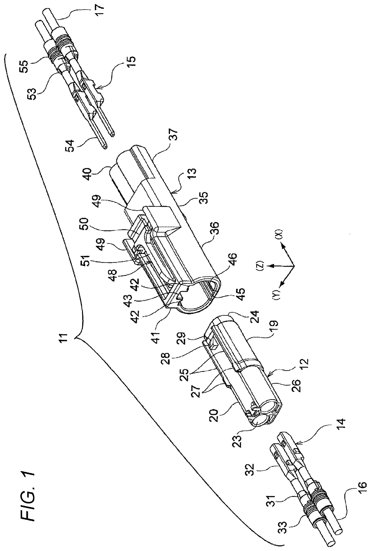
[0029]Hereinafter, a first embodiment of a connector according to the invention will be described with reference to the drawings. As illustrated in FIG. 1, a connector 11 of the first embodiment includes a female housing 12 (one housing) and a male housing 13 (other housing) which are fitted into each other. The connector 11 is configured such that a female terminal 14 housed in the female housing 12 and a male terminal 15 housed in the male housing 13 are electrically connected by fitting the female housing 12 and the male housing 13. Electric wires 16 and 17 are connected with the female terminal 14 and the male terminal 15, respectively. The female housing 12 is configured to be fitted and locked to the inside of the male housing 13 when fitted into the male housing 13. In FIG. 1, each housing houses two terminals. However, the number of the housed terminals is not limited to two. Incidentally, hereinafter, the description will be given with a definition in which an X direction o...

second embodiment

[0061]A second embodiment is different from the first embodiment as follows. As illustrated in FIG. 13A, in the waterproof structure formed by fitting the female-side tubular body 24 and the male-side tubular body 47, an annular protrusion 72 which contacts with the facing surface (not illustrated) of the male-side tubular body 47 is provided over the entire periphery in a facing surface 71 of the female-side tubular body 24 of the facing surfaces of the female-side tubular body 24 and the male-side tubular body 47, and an inclined surface 73 of which the projection height is lowered from the front end side of the female-side tubular body 24 toward the rear end side is formed in the annular protrusion 72.

[0062]In the second embodiment, the annular protrusion 72 is provided in the facing surface 71 of the female-side tubular body 24. Thus, when the female-side tubular body 24 and the male-side tubular body 47 are fitted to each other, the annular protrusion 72 is pushed against the f...

third embodiment

[0066]A third embodiment is different from the first embodiment as follows. In the waterproof structure formed by fitting the female-side tubular body 24 and the male-side tubular body 47, only the projecting length of the male-side tubular body 47 to the front side is lengthened. FIGS. 14A and 14B are views illustrating a state where the female-side tubular body 24 and the male-side tubular body 47 are fitted. In FIGS. 14A and 14B, the projecting length of the female-side tubular body 24 to the front side is the same as a length (lap length) in the front and rear direction where the outer peripheral surface of the female-side tubular body 24 contacts with the inner peripheral surface of the male-side tubular body 47.

[0067]As illustrated in FIG. 14A, a projecting length L3 of the male-side tubular body 47 to the front side is set longer than a projecting length L4 of the male-side tubular body 47 to the front side illustrated in FIG. 14B. Thus, the female-side tubular body 24 can be...


PUM


Abstract

A connector includes a pair of housings to be fitted to each other by inserting an insertion part of one housing into a tubular part of another housing. On an outer peripheral surface of the insertion part of the one housing, a plurality of outer ribs which project from the outer peripheral surface are provided separately in a circumferential direction to extend from a front end of the insertion part to a rear side. On an inner peripheral surface of the tubular part of the other housing, a plurality of inner ribs which project from the inner peripheral surface are provided separately in a circumferential direction to extend from a front end of the tubular part to a rear side. The outer ribs and the inner ribs are provided such that positions in the circumferential direction are deviated from each other.

Description

CROSS-REFERENCES TO RELATED APPLICATIONS[0001]This application is a continuation of International Application No. PCT / JP2017 / 021827 filed on Jun. 13, 2017 based on Japanese Patent Application No. 2016-137219 filed on Jul. 12, 2016, the contents of which are incorporated herein by reference.TECHNICAL FIELD[0002]The present invention relates to a connector.BACKGROUND ART[0003]A connector of JP-A-2013-239369 includes a pair of housings in which an insertion part of one housing is inserted and fitted to a tubular part of the other housing. In such a kind of connector, the clearance (gap) between the outer peripheral surface of the insertion part and the inner peripheral surface of the tubular part is properly set to regulate looseness between the housings.SUMMARY[0004]In the connector of JP-A-2013-239369, typically, the clearance between the outer peripheral surface of the insertion part and the inner peripheral surface of the tubular part is set properly. However, depending on the clea...

Claims


Application Information

Patent Timeline
Patent Type & Authority Patents(United States)
IPC IPC(8): H01R13/52H01R13/631H01R13/627H01R13/50H01R13/64H01R13/422H01R13/629H01R43/18
CPCH01R13/631H01R13/6272H01R13/5221H01R13/64H01R13/50H01R13/5219H01R43/18H01R13/629H01R13/4223
Inventor OISHI, KOZOMIYAKAWA, TOMOYUKI
Owner YAZAKI CORP
Why Eureka
Try Eureka