Sliding device used on the supporting shaft

a sliding device and supporting shaft technology, applied in the direction of machine supports, couplings, rod connections, etc., can solve the problems of inconvenient use, unsteady locking of the sliding base, inconvenient use, etc., to avoid excess pressing, prolong the useful life, and ensure the effect of safety

Inactive Publication Date: 2011-01-25
XIE WENCANG +1
View PDF15 Cites 60 Cited by
  • Summary
  • Abstract
  • Description
  • Claims
  • Application Information

AI Technical Summary

Benefits of technology

[0012]an elastic body that is connected to the bolt and the sliding base has an elasticity that can make the bolt be pushed and keep at the first position; and
[0023]Comparing with the related art and aiming at the disadvantages of the related art, the present applicant invents a new technical solution, which utilizes the button to achieve singlehanded operation, utilizes horizontal slide of the bolt to achieve the steady locking of tiny clearance(this tiny clearance is smaller than the clearance in the related art), utilizes the active connection with relative turn and relative slide between the sliding base and the button to achieve transmission between the pressing of users and the horizontal slide of the bolt. The button face is parallel to the supporting shaft when it is pressed to the end, which is convenient for users controlling pressing limit to avoid excess pressing and prolongs useful life. The inner end part of the bolt is matched with the locking hole and the inner small hole to achieve match of tiny clearance. The spring is covered on the bolt directly, so when the bolt is at the first position, the spring acts on the bolt directly, which has a good security. In pressing the button it needs not acting on the spring directly, but pulls the bolt by the button; the horizontal slide of the bolt acts on the spring to make the spring be pressed, so the spring is not destroyed easily and has a long useful life to ensure that the bolt has a good locking effect.

Problems solved by technology

The sliding device has disadvantages as follows: in using users must pull the pull ring to overcome the elasticity of the elastic body to make the bolt get out of the locking hole and the sliding base can slide freely with one hand and fasten the sliding base to make the sliding base slide against the supporting shaft with the other hand, which must be handled with two hands, to make it be inconvenient for using.
Firstly, as a result of that the movement track of the pull part of the bolt is circular arc, the movement track of the bolt is not a simple aclinic movement but a complicated curve track. So the aperture of the locking hole must be bigger than the outside diameter of the bolt, which makes locking of the sliding base be unsteadily. Even at the state of locking the sliding base can slide along the supporting shaft in some sort, and the sliding distance is diameter difference of the aperture of the locking hole and the outside diameter of the bolt. The bolt also has a complicated inserting track, which is not inconvenient for inserting and can bring blocking phenomena.
Secondly, the elastic body is installed between the backside of the button part and the sliding base. Because there is no orientation shaft for being covered for the elastic body, so the elastic body cannot be fastened. In setting the elastic body twists easily to result in that it is inconvenient for using and has a short life. Even there is orientation shaft, but because the orientation shaft also has a complicated movement curve, so the elastic body will also twist in compressing or elongate.
Thirdly, spring is set on the button part, in normal state the spring drives the button firstly, then the button drive the bolt to ensure that the bolt is at the first position, which has a bad orientation effect. Besides, in pressing the button the users press the spring directly. As a result of that different users have different strength, the spring is easily destroyed and loses its elasticity and its locking function.

Method used


Image

  • Sliding device used on the supporting shaft
  • Sliding device used on the supporting shaft
  • Sliding device used on the supporting shaft

Examples


embodiment 1

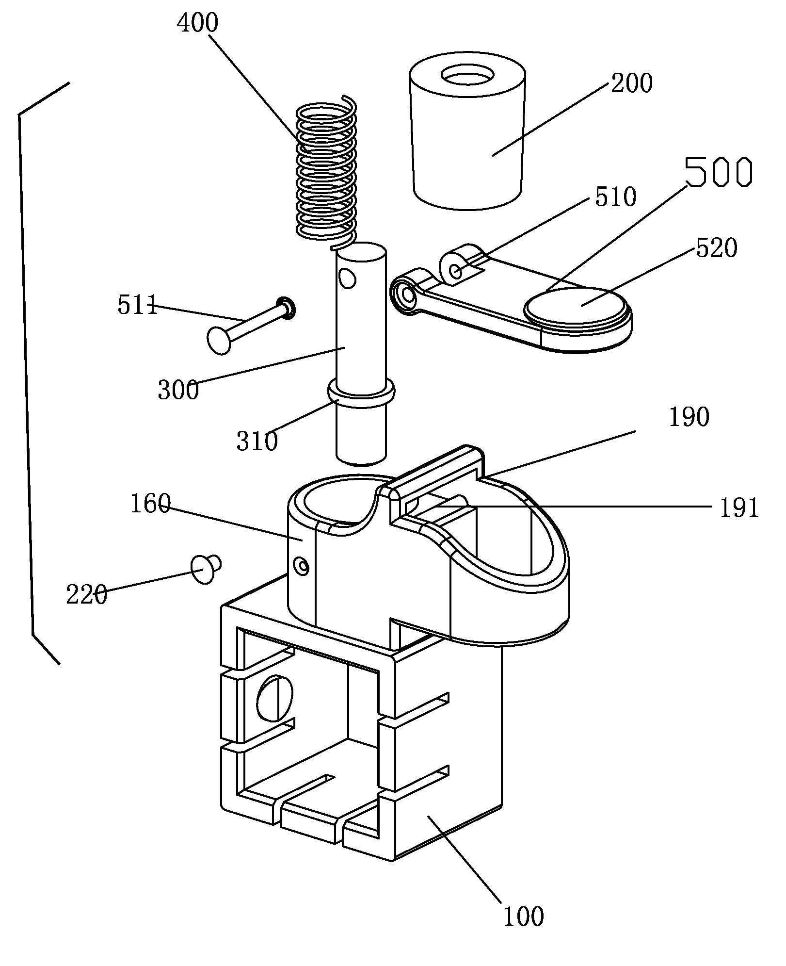
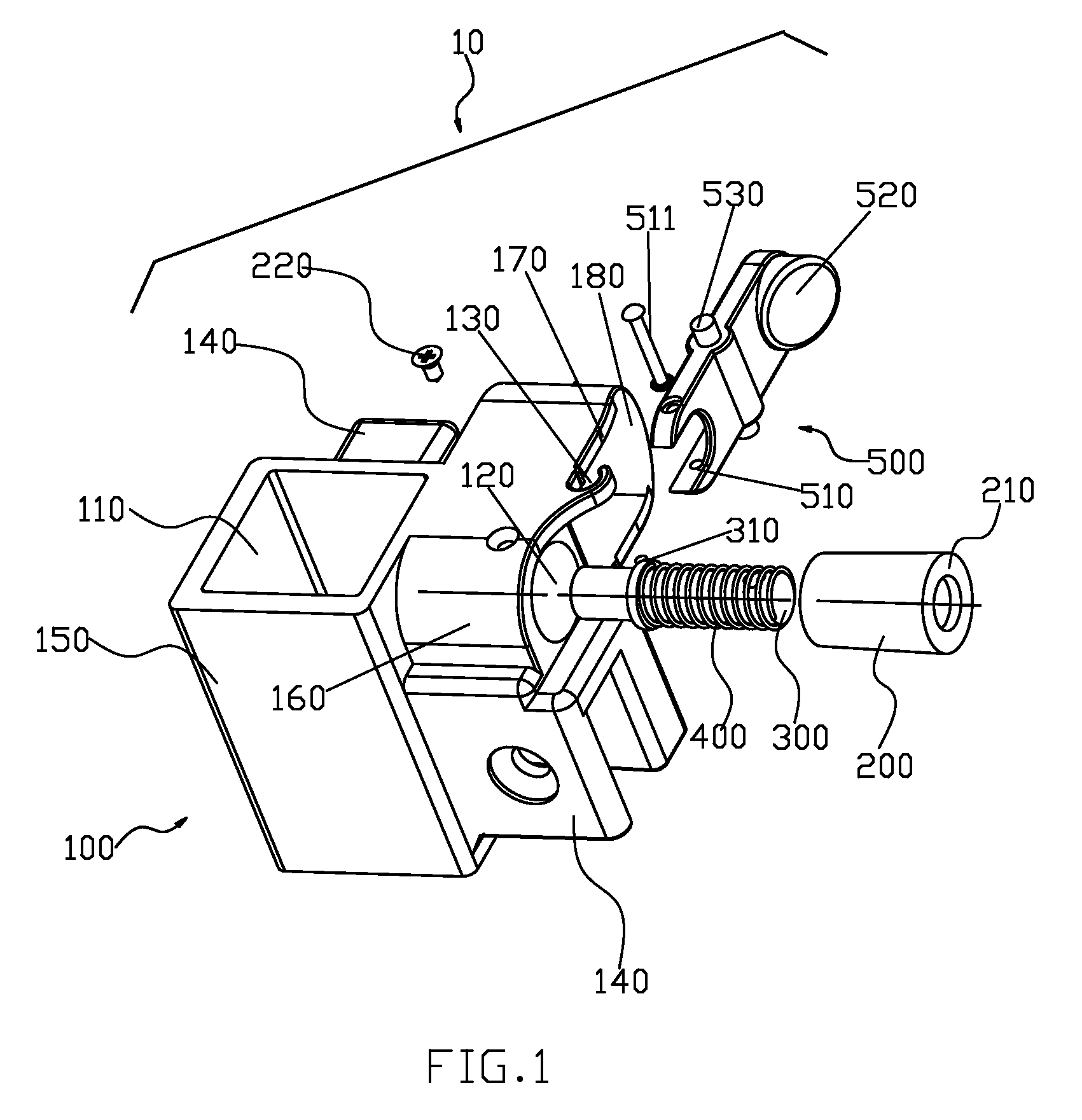
[0033]Referring to FIGS. 1 to 4, the sliding device 10 comprises a sliding base 100, an orientation sleeve 200, a bolt 300, an elastic body 400 and a button 500.

[0034]The sliding base 100 comprises a sliding through hole 110 through upside and downside, a main sleeve 150 encircling the sliding through hole 110, a horizontal mounting hole 120 through inside and outside, a side sleeve 160 encircling the mounting hole 120 and fixed to a side of the main sleeve 150, at least two connecting parts 140 that are fixed to the outside of the main sleeve 150 and are used to being connected to the forficiform connecting rod, two disjunct basal walls 170 that are fixed to sides of the main sleeve 150 and beside the side sleeve 160, and a back wall 180 that is fixed to the two basal walls 170. Wherein the sliding through hole 110 is fittingly covered on the supporting shaft slidably to make the sliding base 100 and the supporting shaft form a sliding connection up and down. The mounting hole 120 ...

embodiment 2

[0043]Referring to FIG. 5, the mounting slot 130 has an upward mouth. The pull part 510 is a ring, which covers the outer end part that the bolt 300 protrudes outside of the ringed lid 210, and there is a rivet 511 to get through the pull part 510 and the outer end part.

embodiment 3

[0044]Referring to FIGS. 6 and 7,the present embodiment has differences with the embodiment 1 as follows: Installation modes of the button 500 and the sliding base 100 are different. The upside of the sliding base 100 has a mounting slot 190 that the button 500 can get through. The mounting slot 190 has a raised platform 191. The clearance of the mounting slot 190 is bigger than the thickness of the button 500 to make the button 500 and the sliding base 100 form an active connection with relative turn and relative slide synchronously.

[0045]In normal state, the bolt 300 is at a first position at the effect of the spring 400; here the bolt 300 is inserted into the locking hole of the supporting shaft to be fixed to the first position. When the bolt 300 is needed to be withdrew, the button 500 is pressed, and the pull part of the button pulls the button 300 upwards utilizing a pivot namely the raised platform 191 of the mounting slot 190 to make the bolt 300 being positioned to a secon...


PUM


Abstract

The present invention discloses a sliding device used on the supporting shaft, which utilizes the button to achieve singlehanded operation, utilizes horizontal slide of the bolt to achieve the steady locking of tiny clearance, and utilizes the active connection with relative turn and relative slide between the sliding base and the button to achieve transmission between the pressing of users and the horizontal slide of the bolt.

Description

FIELD OF THE INVENTION[0001]The present invention relates to a sliding device used on the supporting shaft, particularly to a sliding device used on the supporting shaft of the folding tent.RELATED ART[0002]The supporting shaft of the tent generally has a sliding device for connecting to other parts of the tent. The supporting shaft can be supporting leg for supporting the tent or top supporting shaft at the center of the top of the tent. The supporting shaft is generally pipe piece and has a locking hole through inside and outside. Early sliding device comprises a sliding base, a bolt, an elastic body and a pull ring. The sliding base has a sliding through hole and a mounting hole through inside and outside, and the sliding through hole is covered on the supporting shaft, and the mounting hole and the sliding through hole are orthogonal and connected to each other. The bolt is installed in the mounting hole and slides between a first position and a second position; at the first pos...

Claims


Application Information

Patent Timeline
Patent Type & Authority Patents(United States)
IPC IPC(8): E04H15/32F16B7/14
CPCE04H15/46E04H15/50Y10T403/595Y10T403/7077Y10T403/32483
Inventor XIE, WENCANG
Owner XIE WENCANG
Why Eureka
Try Eureka