
Roller blind with noiseless flat spiral spring drive

Inactive Publication Date: 2011-01-25
BOS
View PDF42 Cites 19 Cited by
  • Summary
  • Abstract
  • Description
  • Claims
  • Application Information

AI Technical Summary

Benefits of technology

[0010]When the spring motor is running, an intermediate area is formed in which the spring windings do not lie against each other, but instead are clearly spaced apart from each other. This area moves while the spring motor runs in the radial direction through the pot-shaped housing of the spring motor. When the spring windings transition through this loose area, heretofore it could lead to radial vibrations of the spring windings, with the spring windings striking each other and generating noise. The damping plate damps the radial vibrations.

Problems solved by technology

When the spring windings transition through this loose area, heretofore it could lead to radial vibrations of the spring windings, with the spring windings striking each other and generating noise.

Method used


Image

  • Roller blind with noiseless flat spiral spring drive
  • Roller blind with noiseless flat spiral spring drive
  • Roller blind with noiseless flat spiral spring drive

Examples


Embodiment Construction

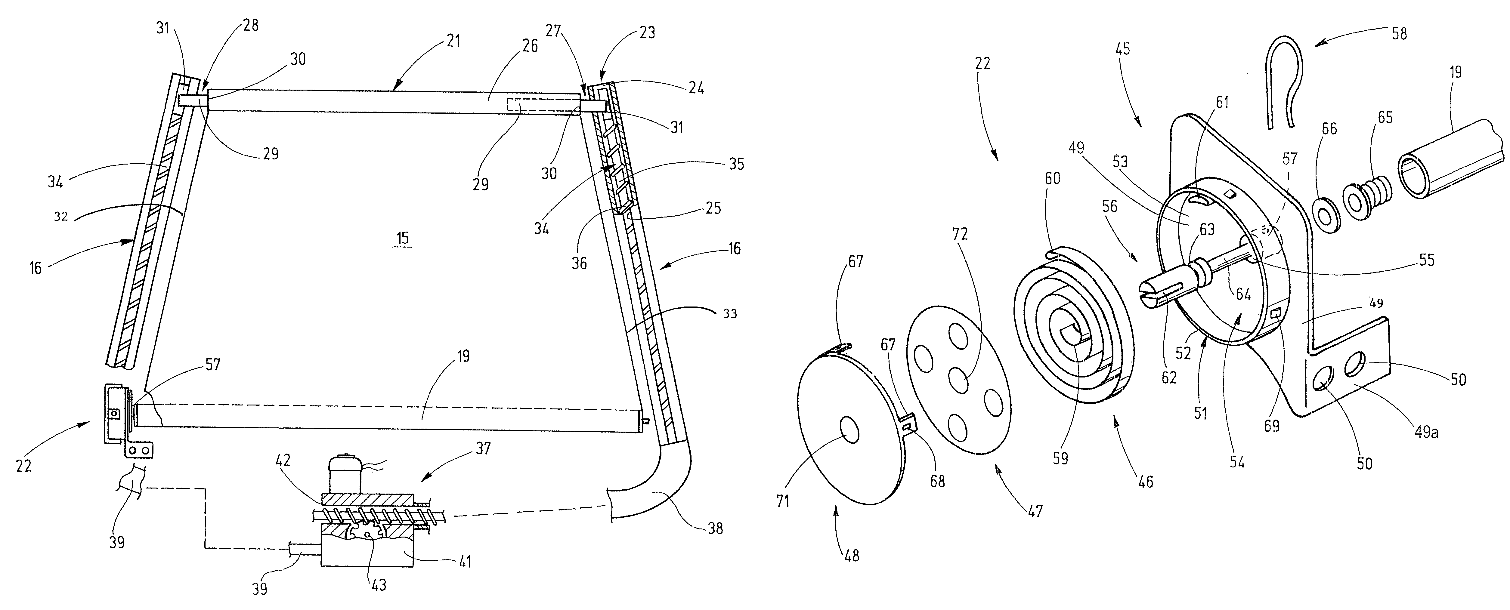
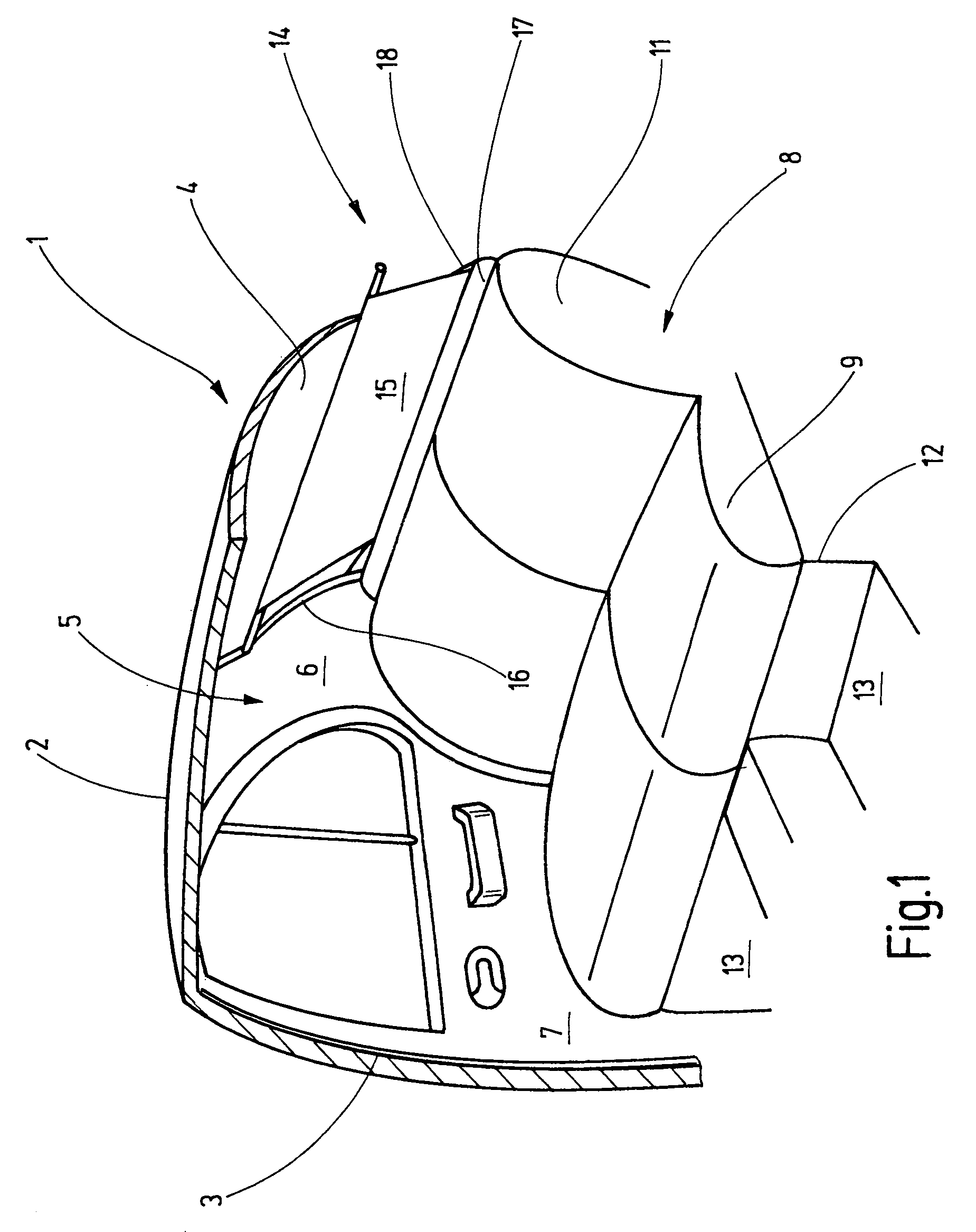
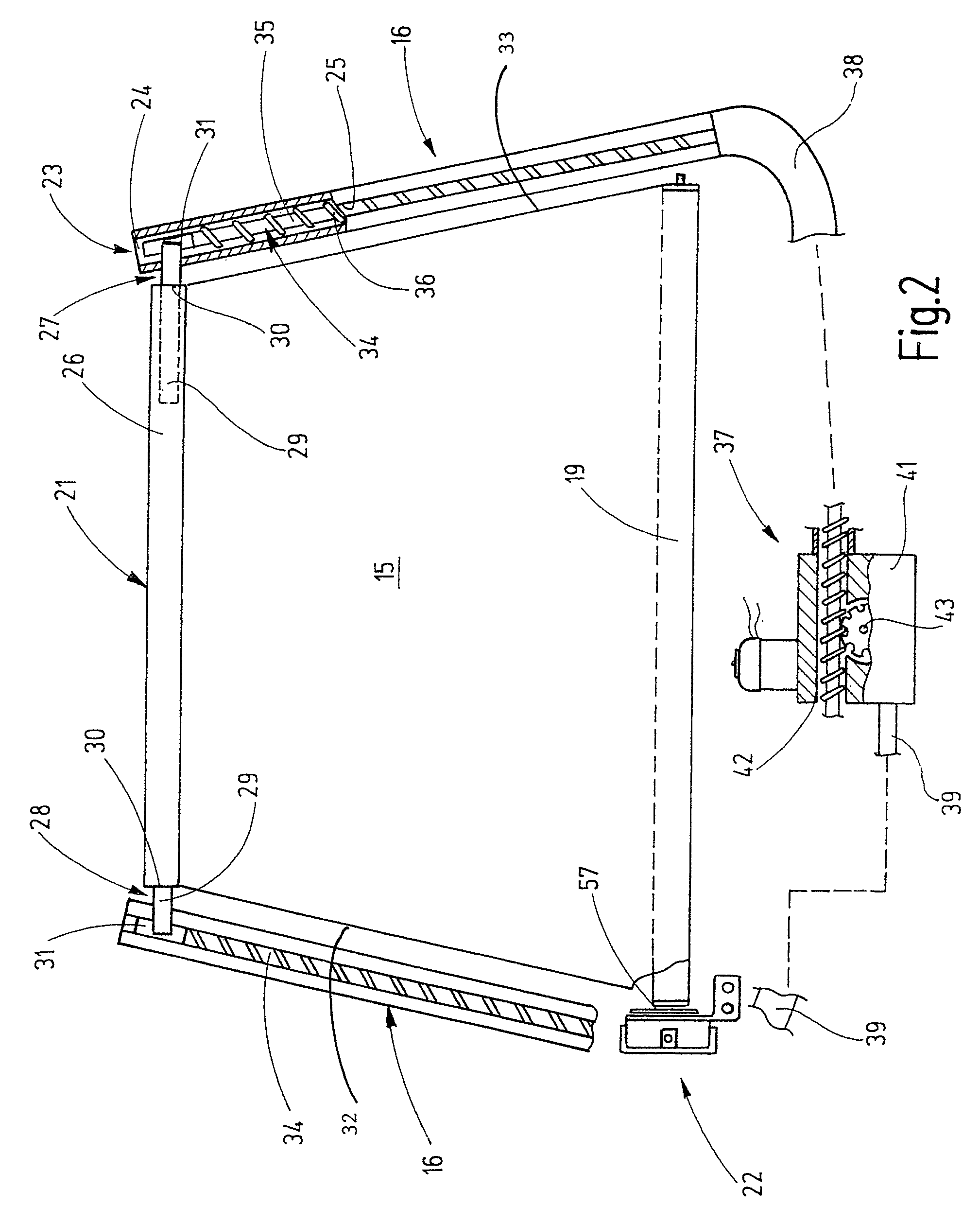
[0027]Referring now more particularly to FIG. 1 of the drawings, there is shown an illustrative passenger vehicle body or chassis section 1 having a rear window roller blind assembly 14 in accordance with the invention. FIG. 1 represents a cut away area of a passenger car, viewed towards the right side interior which is mirror image of the left side interior. The representation is simplified, for example, internal chassis structures, such as reinforcements and attachment means are not shown because the representation is not required for an understanding of the invention.

[0028]The illustrated chassis section 1 has a roof 2 from which B-columns 3 extend downwardly on opposing sides to a floor assembly of the vehicle. The roof 2 transitions at its rear edge into a rear window 4. At the side, the rear window 4 ends at C-columns 5, which are located at a distance to the B-columns 3. The C-column 5 carries an inner lining 6. The width of the rear window 4 is smaller in the vicinity of the...


PUM


Abstract

A spring motor having a pot shaped housing in which a flat spiral spring is housed. The flat spiral spring is connected at one outer end to the pot-shaped housing while the inner end is coupled to a shaft or axle. To prevent radial vibrations of individual spring layers when the spring motor is wound or unwound, a damping plate is housed in the pot-shaped housing and held in pressed engagement with a side edge of the flat spiral spring. This spring motor can be combined with the wind-up shaft of roller-blind arrangements for motor vehicles, including fixed roller blinds, storage-area covers, or separating screens.

Description

FIELD OF THE INVENTION[0001]The present invention relates generally to window roller blinds for motor vehicles, and more particularly, to motor vehicle window roller blinds that are automatically extendable and retractable.BACKGROUND OF THE INVENTION[0002]For shading vehicle windows, it is known to use roller-blind arrangements. The roller blinds have a wind-up shaft which is mounted in the vehicle and to which the shade material is attached with one edge. With the aid of the drive device, the shade material is unwound from the wind-up shaft. Various gear devices are known for the drive.[0003]For a different group of window roller blinds, the unwinding of the shade material is effected manually, in that a handle attached to the front edge of the shade material is grasped and guided away from the wind-up shaft. Here, the front edge of the shade material is understood to be the edge that extends the greatest distance in the pulling-out motion.[0004]The roller blind is typically wound ...

Claims


Application Information

Patent Timeline
IPC IPC(8): B60J1/18A47G5/02E06B9/56
CPCB60J1/2027B60J1/2033B60J1/208B60R21/08E06B9/42B60R5/047E06B9/78E06B9/60B60J3/00B60J1/20
Inventor HANSEN, MELF
Owner BOS
Learn More