Ink-feeding device and pressure-generating method

a technology of pressure generation and feeding device, which is applied in the field of pressure generation method and feeding device, can solve the problems of increasing the negative pressure in the printing head, affecting the recording quality, so as to improve the recording quality, improve the freedom degree of constructing the entire apparatus, and improve the recording quality

Inactive Publication Date: 2011-01-25
COPYER
View PDF17 Cites 32 Cited by
  • Summary
  • Abstract
  • Description
  • Claims
  • Application Information

AI Technical Summary

Benefits of technology

[0007]Such fluctuation of the negative pressure in the printing head may make instable the ink ejection from the printing head to lower the quality of the recorded image. In particular, in printing apparatuses for industrial uses for printing an image at a high speed on a large recording medium, the amount of the ink ejected from the printing head per unit time varies widely, which can cause fluctuation of the negative pressure in the printing head. Therefore, the fluctuation of the negative pressure in the printing head should be minimized to keep high recording quality.
[0018]A first embodiment of the ink-feeding device of the present invention is capable of adjusting the pressure in the printing head by a pressure-adjusting means to adjust arbitrarily the pressure applied to the ink in the printing head irrespective of the placement positions of the ink container and the printing head. The pressure-adjusting means, which is capable of adjusting arbitrarily the pressure applied to the ink in the printing head, keeps the pressure at a constant negative pressure to improve the recording quality. Further, since the relative positions of the ink container and the printing head are not limited, the freedom degree in constructing the entire apparatus is increased.
[0019]A second embodiment of the ink-feeding device of the present invention allows an ink to circulate in an ink circulation channel by driving a circulation pump, whereby the ink circulates between an ink container and a liquid chamber. This circulation generates a negative pressure by a pressure loss in the ink circulation channel. The generated negative pressure is applied to the liquid chamber to keep the pressure acting on the ink in the printing head (ink in the nozzle) to be negative within a suitable range to improve the recording quality. Since the relative positions of the ink container and the printing head are not limited, the freedom degree in constructing the entire apparatus is increased. Further, a bubble existing in the ink in the liquid chamber can be removed from the liquid chamber by return of the ink by circulation to the ink container, which stabilizes more the ink ejection.

Problems solved by technology

Therefore, when the amount of the ink ejected from the printing head per unit time is increased suddenly, the ink feed cannot follow the increase, which may result in increase of the negative pressure in the printing head (the negative pressure applied to the ink in the printing head becomes more than the prescribed pressure).
Such fluctuation of the negative pressure in the printing head may make instable the ink ejection from the printing head to lower the quality of the recorded image.
In particular, in printing apparatuses for industrial uses for printing an image at a high speed on a large recording medium, the amount of the ink ejected from the printing head per unit time varies widely, which can cause fluctuation of the negative pressure in the printing head.
However, for utilizing the water head difference, the relative positions of the sub-tank and the printing head are limited as mentioned above, which decreases significantly the freedom degree in constituting the entire apparatus.

Method used


Image

  • Ink-feeding device and pressure-generating method
  • Ink-feeding device and pressure-generating method
  • Ink-feeding device and pressure-generating method

Examples


example 1

[0060]An example of the printer which incorporates the ink-feeding device of the present invention is explained by reference to FIG. 1.

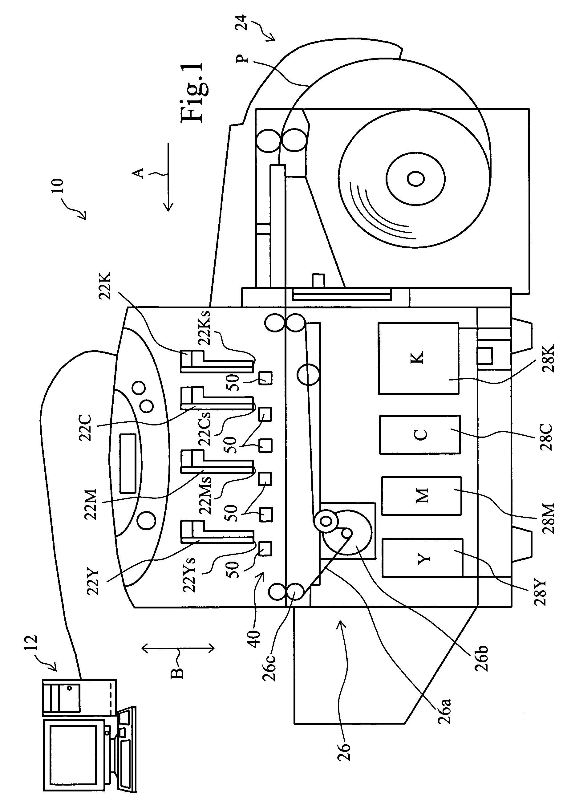
[0061]FIG. 1 is a schematic front view of a printer incorporating an ink-feeding device of the present invention.

[0062]A printer 10 is connected to a host PC (personal computer) 12 for transmitting image information to this printer 10. In the printer 10, four printing heads 22K, 22C, 22M, 22Y are installed in a line in a direction (arrow-A direction) of delivery of a recording medium (a rolled paper sheet in this Example). The four printing heads 22K, 22C, 22M, 22Y eject respectively a color ink of black, cyan, magenta, or yellow. The four printing heads 22K, 22C, 22M, 22Y are so-called line-heads extending perpendicular to the paper sheet face of FIG. 1 (perpendicular to the arrow-A direction). The lengths of the four printing heads 22K, 22C, 22M, 22Y (length perpendicular to the paper sheet face of FIG. 1) are a little larger than the largest bread...

example 2

[0109]In Example 1, the sub-tank 80 is placed higher than the printing head 22K, but the placement is not limited thereto in the present invention. In this Example, an ink-feeding device 160 is explained in which the sub-tank 80 is placed lower than the printing head 22K by reference to FIG. 13.

[0110]FIG. 13 illustrates schematically the ink-feeding device of this Example 2. In this FIG. 13, the same reference numbers and symbols as in FIG. 3 are used for indicating corresponding elements.

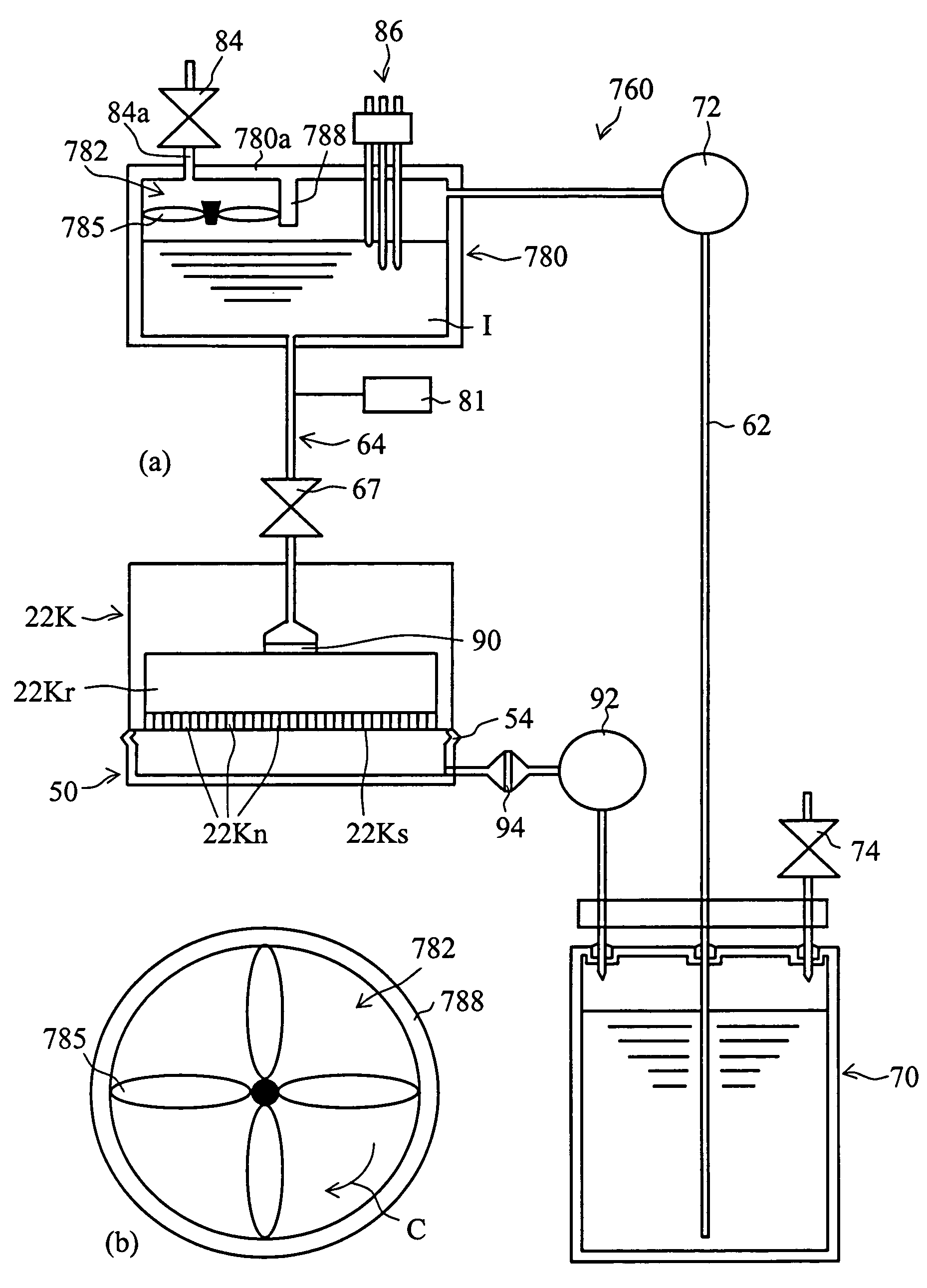
[0111]In the ink-feeding device 160 in this Example 2, sub-tank 80 is placed lower than the printing head 22K. Even in such a positional relation, a pressure-adjusting pump 82 is useful for applying a positive pressure from the outside to keep a suitable negative pressure in the printing head 22K. In this Example, a centrifugal pump is used as the pressure-adjusting pump 82. The shape of the sub-tank 80 shown in FIG. 3 is not suitable for the centrifugal pump to apply sufficient positive pressure t...

example 3

[0113]Example 3 is explained by reference to FIG. 14.

[0114]FIG. 14 is a schematic drawing of the ink-feeding device of this Example 3. In this drawing, the same reference numbers and symbols as in FIG. 6 are used for indicating corresponding elements.

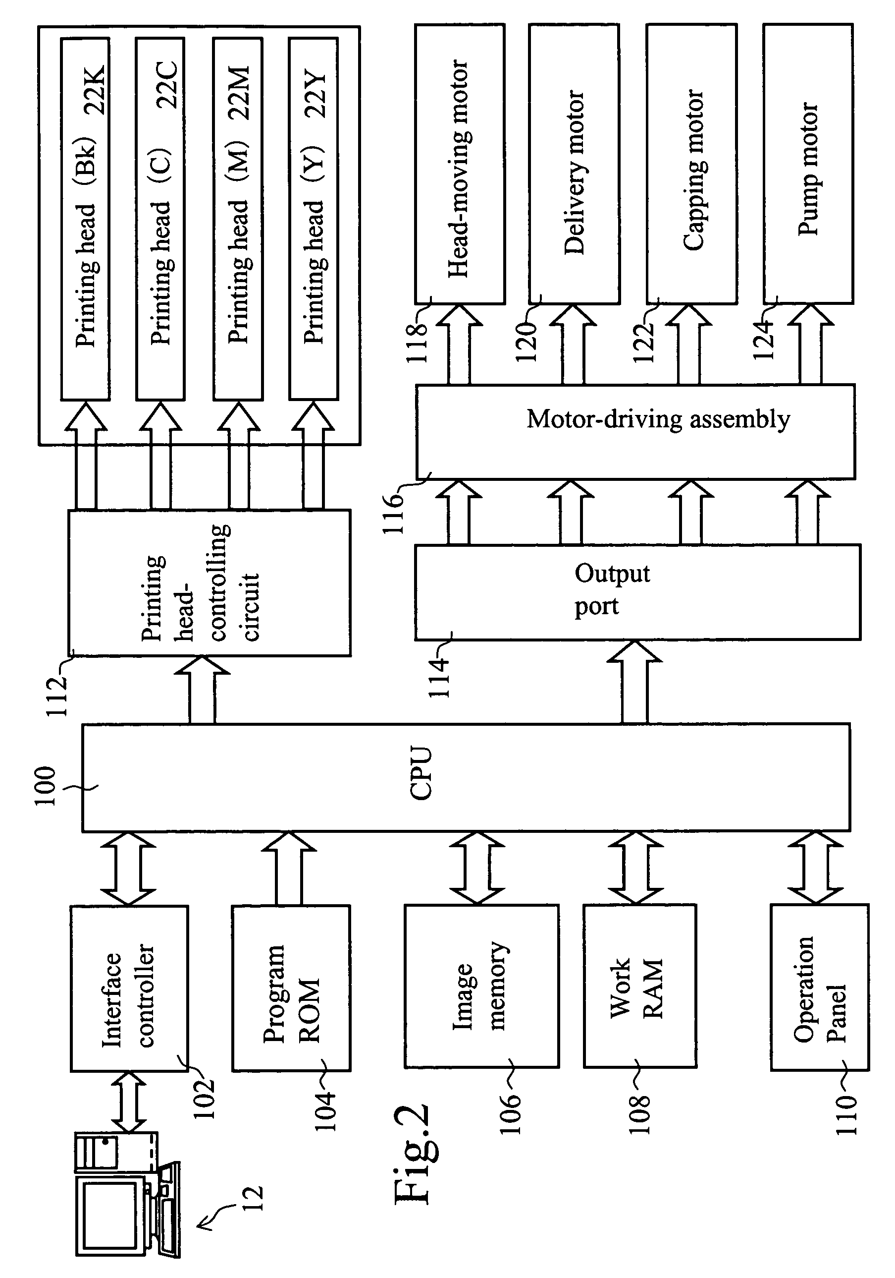
[0115]In the above Example 1, the rotation frequency of the blade 82a (FIG. 7) of the pressure-adjusting pump 82 is changed for controlling the negative pressure in the printing head 22K. In contrast, in the ink-feeding device 170 of this Example 3, the shaft 172 is made movable vertically (in the arrow-D direction) with the blade 82a of the pressure-adjusting pump 82 fixed to the shaft 172. The pressure is controlled by changing the position of the blade 82a: the blade 82a is rotated at a constant rotation frequency by a driving unit 174.

[0116]The shaft 172 has a rack 172a. A pinion gear 172b is engaged with the rack 172a. The rotation of the pinion gear 172b is controlled by a CPU (FIG. 2). The driving force of the driving unit 174 is...


PUM


Abstract

An ink-feeding device is provided in which the pressure applied to the ink in the printing head can be adjusted arbitrarily irrespective of the relative positions of the ink container and the printing head. Inside the sub-tank 80, a pressure-adjusting pump 82 is installed for applying a suitable pressure to many nozzles 22Kn of the printing head 22K. This pressure-adjusting pump 82 is placed a little above the bottom face of the sub-tank 80 at a prescribed distance from the bottom face. Thereby the pressure-adjusting pump 82 is immersed in the ink held in the sub-tank 80. A drive unit 83 for driving the pressure-adjusting pump 82 is placed above the sub-tank 80. On the upper wall of the sub-tank 80, an air-vent valve 84 is fixed to bring the inside pressure in the sub-tank 80 to an atmospheric pressure. The inside pressure in the sub-tank 80 is made equal to the atmospheric pressure by opening the air-vent valve 84.

Description

TECHNICAL FIELD[0001]The present invention relates to an ink-feeding device for feeding an ink to a printing head for ejecting an ink, and relates also to a method for generating a pressure in the printing head.TECHNICAL BACKGROUND[0002]Inkjet types of image-forming apparatuses (inkjet recording apparatuses) are known which form an image by ejecting an ink through a printing head onto a recording medium. Generally, the inkjet image-forming apparatus is capable of forming a highly fine image by employing a small printing head having ink-ejection nozzles in a high nozzle density. The inkjet image-forming apparatus is capable of forming a color image on a recording medium by employing a plurality of the small printing heads and using different color inks for the printing heads with a less expensive smaller constitution. Owing to the above advantages, the inkjet image-forming apparatuses are widely used as various image output apparatuses such as printers, facsimiles, and copying machin...

Claims


Application Information

Patent Timeline
Patent Type & Authority Patents(United States)
IPC IPC(8): B41J2/175
CPCB41J2/17556
Inventor OTA, NORITAKATAKAHASHI, YUICHINAKAMURA, DAISUKEMIURA, TAKESHIHAIDA, KAZUO
Owner COPYER
Why Eureka
Try Eureka