
Recessed lighting fixture with multiple adjustment axes

a technology of recessed lighting and adjustment axes, which is applied in the direction of fixed installation, lighting and heating equipment, lighting support devices, etc., can solve the problems of limited ability to control the direction of illumination efficiently and easily, and the incongruity of most in-ground light fixtures with the surrounding vegetation, so as to reduce glare, easy to install, and easy to remove for maintenance or modification

Active Publication Date: 2011-01-25
HUNTER INDUSTRIES
View PDF49 Cites 84 Cited by
  • Summary
  • Abstract
  • Description
  • Claims
  • Application Information

AI Technical Summary

Benefits of technology

[0009]It is an advantage of the present invention to provide recessed (in ground or in wall) lighting fixture that permits adjustment on at least three different axes for controlling the light beam emitted from the fixture.
[0010]It is an additional advantage of the present invention to provide a recessed lighting fixture that is waterproof and capable of being fully submerged in water.
[0011]Still another advantage of the present invention is to provide a recessed lighting fixture that is easily installed and easily removed for maintenance or modification of the properties of light emitted by the fixture.
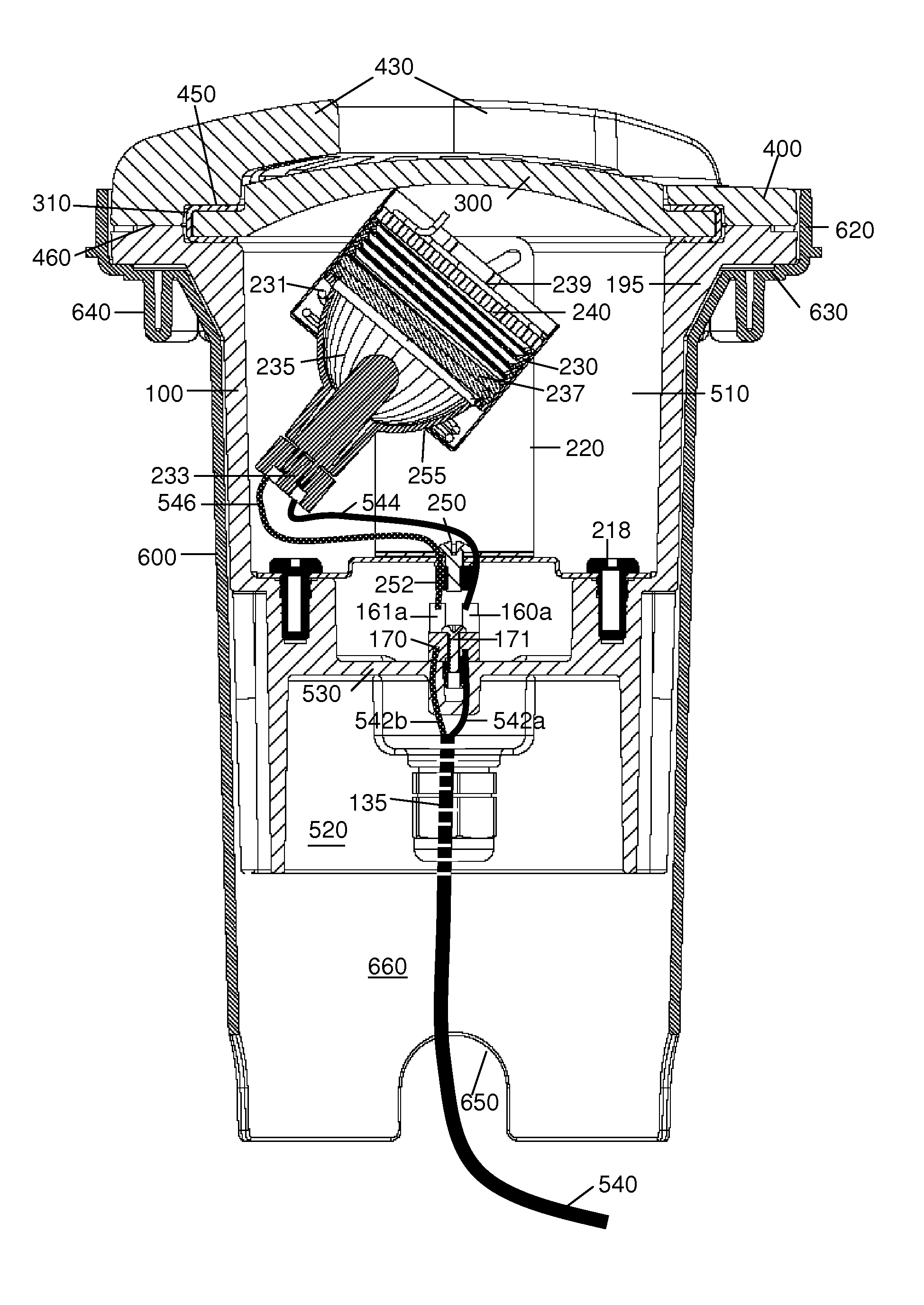
[0012]In an exemplary embodiment, the recessed, or “well light”, fixture comprises a cylindrical housing with an open output end and a closed inner end. The output end has a flange with an annular recess for receiving a lens or window. An O-ring is placed over the edge of the lens and sandwiched between the surface of the annular recess of the flange and a protective cover to provide a watertight seal. The cover may include a pattern of ridges and openings to form a baffle to further protect the lens, reduce glare and provide additional direction of the light.
[0013]In the preferred embodiment, a lamp assembly disposed within the interior of the housing includes an attachment base bracket, and a U-shaped bracket that is rotatably attached to the base bracket. The U-shaped bracket may have an angled slot on each of the upper arms for pivotable attachment of the lamp housing or, alternatively, a separate connector that slides onto the upper arms to allow the lamp housing to travel vertically while allowing the lamp housing to pivot about the attachment points. The combination of the pivot points and their corresponding connectors / slots allows the position of the lamp assembly to be adjusted axially within the housing. The combination of the pivot points and the ability to rotate the lamp housing about the base bracket forms a gimble for varying the angle of the lamp assembly within the housing.
[0014]The lamp housing is a cylindrical enclosure, open at the light output end, for enclosing a lamp socket, a bias spring, a lamp, one or more optional filters, one or more optional spacer rings, a optional diffuser, and a retainer spring. The lamp housing may be formed from high temperature plastic.

Problems solved by technology

Landscape lighting fixtures, most of which are mounted at or above ground level can be considered to appear somewhat incongruous with the surrounding vegetation during daylight hours, when the illumination function is not in use.
Further, because of the constant exposure to the elements, above ground lighting fixtures are generally required to be made of expensive, high quality materials, such as non-corrosive metal alloys, in order to provide durability and a reasonable resistance to damage so as not to appear cheap and unkempt.
Most in-ground light fixtures are not waterproof but are sufficiently water resistant that they may still be placed in wet ground, but not designed to be immersed under water.
A problem experienced with below-ground light fixtures as well as underwater light fixtures is the limited ability to control the direction of illumination efficiently and easily due to the limited range of illumination and convenient access to the lamp.

Method used


Image

  • Recessed lighting fixture with multiple adjustment axes
  • Recessed lighting fixture with multiple adjustment axes
  • Recessed lighting fixture with multiple adjustment axes

Examples


Embodiment Construction

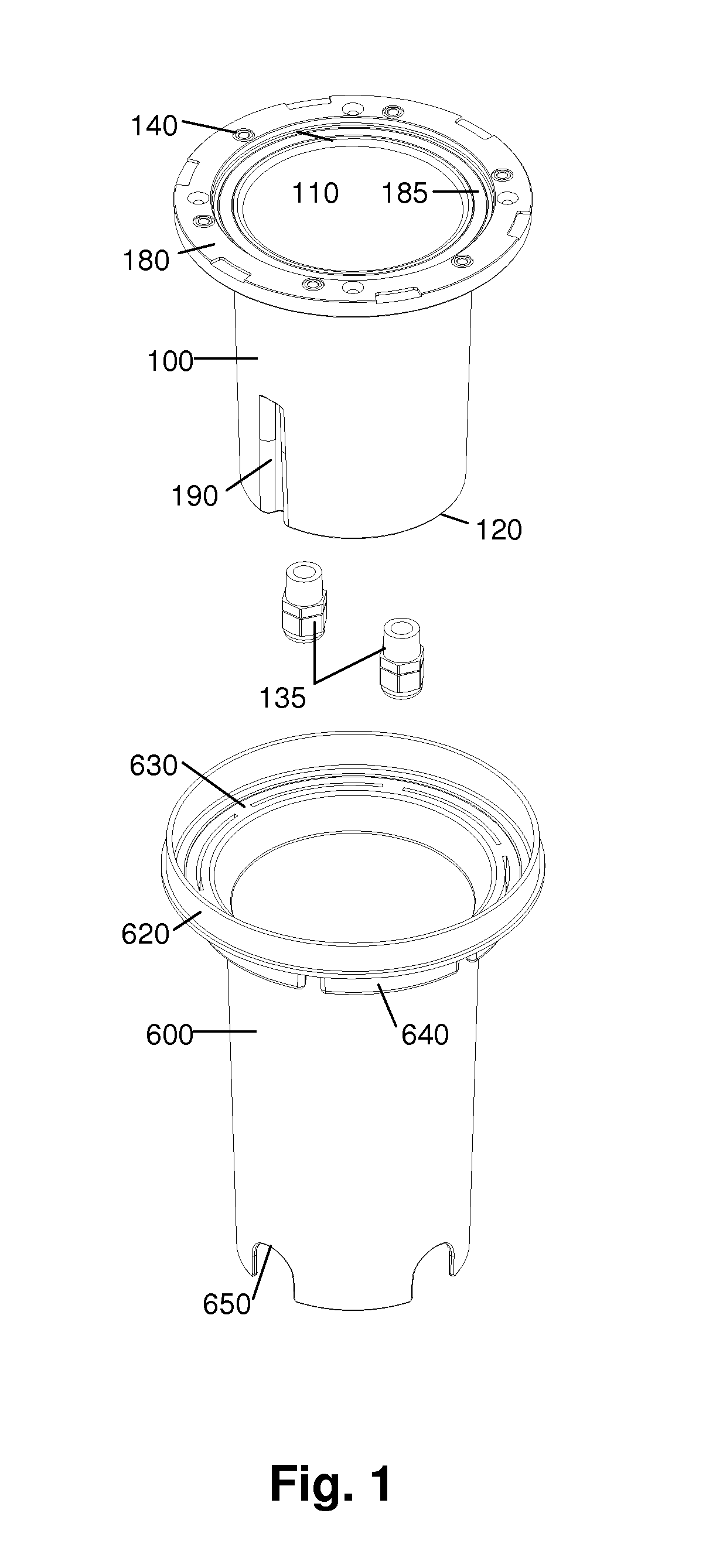
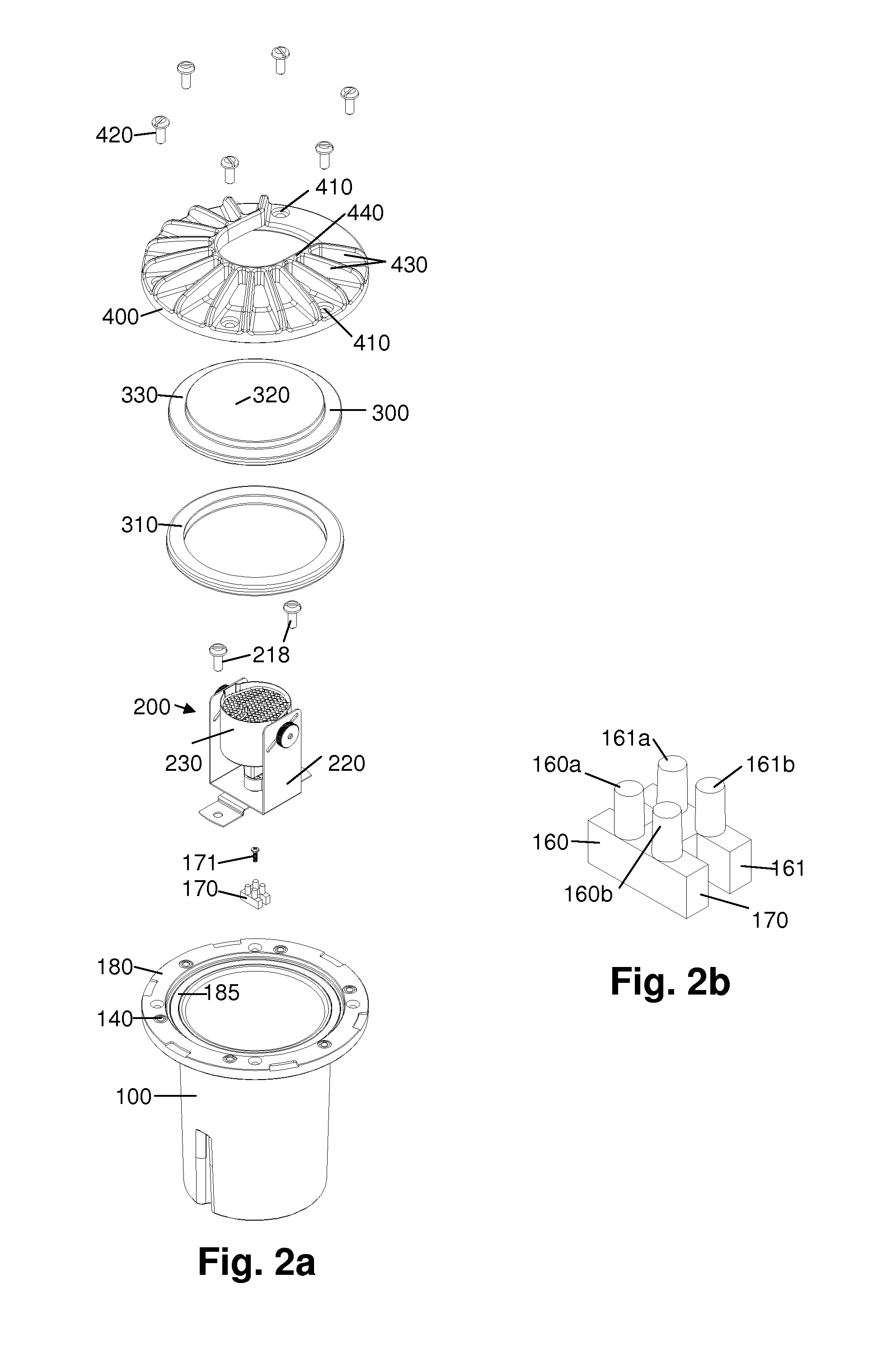
[0043]As illustrated in FIG. 2, a first exemplary embodiment of the in-ground lighting fixture includes cylindrical housing 100, lamp assembly 200, lens 300, and cover 400. The housing 100 is configured to be inserted into a recess, preferably a recess defined by an outer sleeve 600, which is shown in FIG. 1.

[0044]Referring to FIG. 2, cylindrical housing 100 has an outlet end 110, a bottom 120, an outer diameter, and an inner diameter. Housing 100 is shorter than outer sleeve 600 so that a cavity 660 is defined at the bottom of the outer sleeve when housing 100 is installed.

[0045]Flange 180 extends radially from the outer diameter greater than the outer diameter of housing 100 at the top of the outlet end 110 and has an annular recess 185 for supporting lens 300 and cover 400, and rests on top of support flange 630 if the outer sleeve 600 is used. Recess 185 has a depth that is approximately one-half the thickness of lens 300. A plurality of threaded bores 140 are positioned around ...


PUM


Abstract

The recessed fixture includes a cylindrical housing assembly that encloses a lamp assembly in a watertight enclosure. The lamp assembly includes an attachment base bracket attached to the interior of the housing, and a U-shaped bracket that is rotatably attached to the base bracket. The U-shaped bracket includes attachment means that permit vertical and angular adjustment of the lamp assembly relative to the axial center of the housing. The combination of the pivot points and the ability to rotate the lamp housing about the base bracket provides at least three axes of adjustability to permit variation of the character of light emitted from the fixture. A cover placed over the end of the housing seals a lens to the housing to produce a watertight seal. The cover may include a pattern of ridges and openings to form a baffle to further protect the lens, reduce glare and provide additional directional control of the emitted light. The cylindrical housing fits within a sleeve that is positioned generally flush with the surface in which the fixture is being recessed, allowing the fixture to be accessed for installation and maintenance.

Description

RELATED APPLICATIONS[0001]This application claims the priority of U.S. Provisional Application No. 60 / 988,078, filed Nov. 14, 2007, which is incorporated herein by reference in its entirety.FIELD OF THE INVENTION[0002]The present invention relates to lighting fixtures for landscape and environmental lighting applications and, more particularly, to recessed lighting for placement in the ground or in walls.BACKGROUND OF THE INVENTION[0003]The use of outdoor lighting fixtures is becoming increasingly popular for illuminating buildings, gardens, pathways, and entrance ways as the nighttime play of light on the landscape and exterior structures is aesthetically pleasing. Lighting of outdoor ponds, pools, water falls, brooks, streams, and water fountains enhances the overall appeal of outdoor lighting. Additionally, such lighting provides enhanced security by reducing or eliminating dark hiding places and unobserved entry points for intruders. The most widely used outdoor lighting systems...

Claims


Application Information

Patent Timeline
IPC IPC(8): F21V19/02F21V21/26
CPCF21S8/022F21V21/30F21V31/005F21V21/28F21W2131/10
Inventor BEADLE, JOSHUA Z.
Owner HUNTER INDUSTRIES
Learn More