Magnetic disk device
a magnetic disk and disk assembly technology, applied in the direction of electrical apparatus construction details, instruments, record information storage, etc., can solve the problems of difficult estimation, certain air turbulence, and vibration in the disk and head gimbal assembly, and achieve the effect of improving bonding reliability
- Summary
- Abstract
- Description
- Claims
- Application Information
AI Technical Summary
Benefits of technology
Problems solved by technology
Method used
Image
Examples
second embodiment
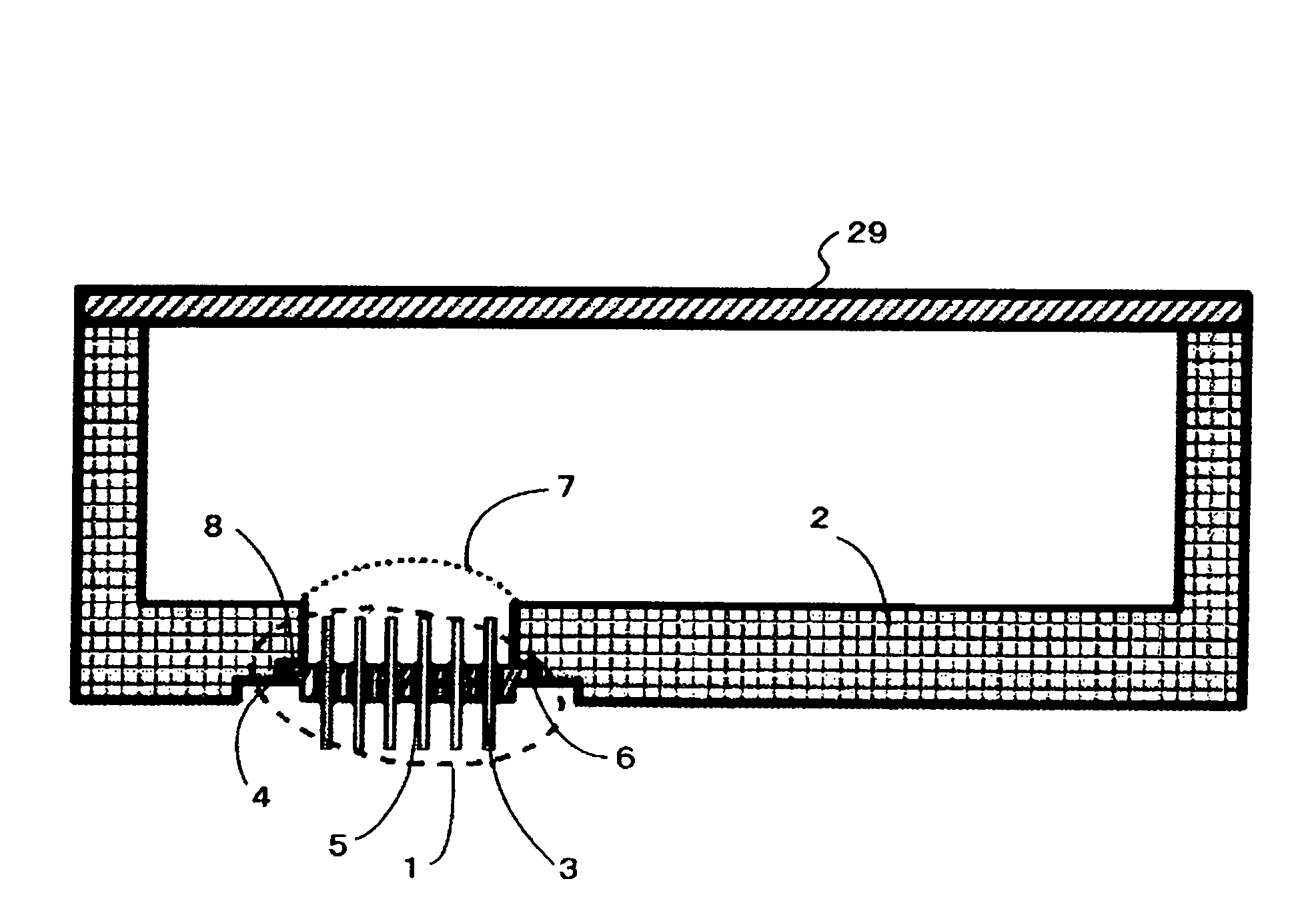
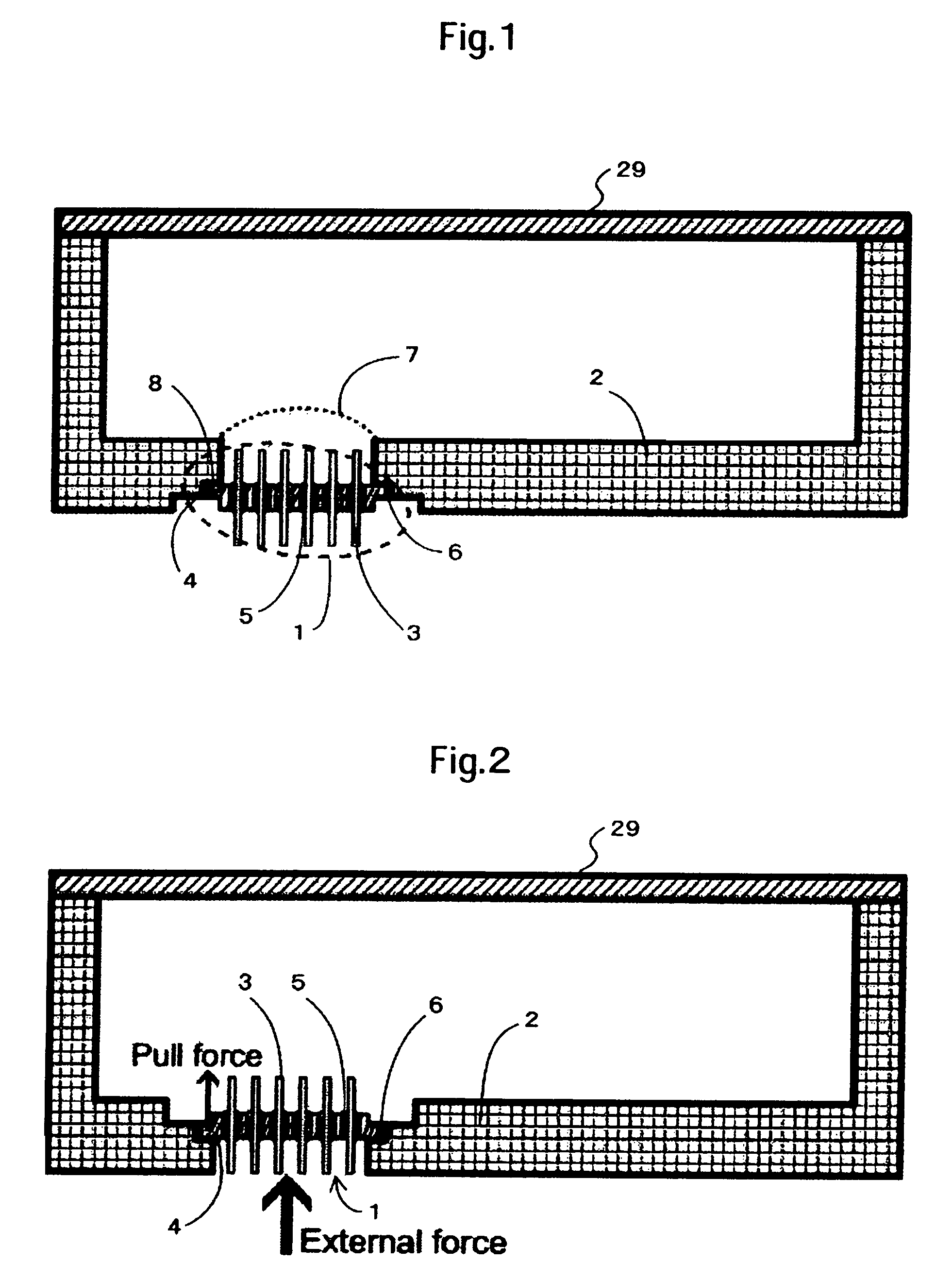
[0051]FIG. 4 shows a cross section of a portion where the feedthrough of the magnetic disk device according to the present invention is mounted. Also in the figure, the HDA shown in FIG. 3B is omitted and the periphery of the feedthrough is enlarged. Incidentally, the feedthrough 1 is substantially the same in total configuration as that shown in FIG. 1.
[0052]As shown in FIG. 4, a step as the feedthrough mounting plane 8 is provided in a position closer to the inside of the device than the center 71 of thickness of the base 2, in other words, if the thickness of the base is taken to be T, the feedthrough mounting plane 8 is situated in the position closer to the inside of the device than the position of T / 2.
[0053]According to the present structure, the feedthrough mounting plane 8 is provided in the position closer to the inside of the device than the center 71 of the thickness of the base 2, which enables changing the direction to which the base 2 is deformed to suppress deformatio...
third embodiment
[0060]FIG. 5 shows a perspective view of a feedthrough according to the
[0061]In the above second embodiment, the deformation of the base 2 offsets that of the feedthrough 2 to suppress the out-of-plane deformation of the flange 4, however, this does not always mean that the out-of-plane deformation thereof is completely suppressed.
[0062]For this reason, as shown in FIG. 5, a ditch 9 is provided in the plane that is the periphery of the flange 4 inside the device.
[0063]According to the present structure, the deformation of the feedthrough can be restricted to the periphery of the ditch and precluded from extending to the whole area. As a result, stress applied to the solder bonding portion 6 can be further suppressed.
[0064]FIGS. 8A and 8B show the states that the feedthrough 1 and the solder bonding portion 6 are deformed due to a change in temperature. FIG. 8A shows results obtained by the finite element method by calculating deformation for cases where temperature is changed from n...
PUM
| Property | Measurement | Unit |
|---|---|---|
| stress | aaaaa | aaaaa |
| radius | aaaaa | aaaaa |
| density | aaaaa | aaaaa |
Abstract
Description
Claims
Application Information
 - R&D
- Intellectual Property
- Life Sciences
- Materials
- Tech Scout
- Unparalleled Data Quality
- Higher Quality Content
- 60% Fewer Hallucinations
Browse by: Latest US Patents, China's latest patents, Technical Efficacy Thesaurus, Application Domain, Technology Topic, Popular Technical Reports.
© 2025 PatSnap. All rights reserved.Legal|Privacy policy|Modern Slavery Act Transparency Statement|Sitemap|About US| Contact US: help@patsnap.com


