Manufacturing method of impeller

a manufacturing method and impeller technology, applied in the direction of manufacturing tools, machines/engines, solventing apparatus, etc., can solve the problems of difficult inserting into the passage, difficult integration molding, and more likely to occur welding defects, so as to ensure the bonding strength increase the reliability of the bonding part. , the effect of more reliable bonding

Active Publication Date: 2010-07-29
MITSUBISHI HEAVY IND LTD
View PDF4 Cites 17 Cited by
  • Summary
  • Abstract
  • Description
  • Claims
  • Application Information

AI Technical Summary

Benefits of technology

[0020]In this case, the cover can be disposed in a stable state by allowing the flat surface of the cover to face down. Accordingly, during the bonding, the bonding material uniformly flows toward the inner peripheral bond part end which is positioned at the curved portion of the passage along the curved surface of the cover or the blade which is formed integrally with the cover. In this aspect, the problem that the bonding material is partially insufficient can be eliminated, therefore more reliable bonding can be performed.
[0021]According to the manufacturing method of an impeller of the present invention, the bonding material which is melted during bonding is bonded while flowing toward the inner peripheral side of the bond part between the blade, and the cover or the disc. Therefore, it is possible to prevent insufficient supply of the bonding material on the inner peripheral bond part end, such that the bonding strength of the bond part can be ensured and the reliability of the bond part can be increased.

Problems solved by technology

However, in the impeller generally provided in the centrifugal compressor, as the passage has a complex shape which is curved in both the axial direction (the rotation shaft direction) and the radial direction, the integral molding is difficult.
In this case, it is necessary to insert a welding torch into a passage, and in a case where the passage is narrow, inserting it into the passage is difficult.
Therefore, there is a problem in that welding defects are more likely to occur.
However, the structure of the existing impeller has the following problems.
Accordingly, when the brazing filler metal 14 disposed between the blade 13 and the disc 11 is melted and liquefied, the brazing filler metal 14 flows from the inner peripheral side toward the outer peripheral side (in an arrow direction G) along the curved surface 11a. Therefore, the brazing filler metal 14 is insufficiently supplied to the inner peripheral side of the bond part, such that there is a problem in that the bonding strength of the bond part on the inner peripheral side, which requires a reliable bonding, is reduced.

Method used


Image

  • Manufacturing method of impeller
  • Manufacturing method of impeller
  • Manufacturing method of impeller

Examples


first embodiment

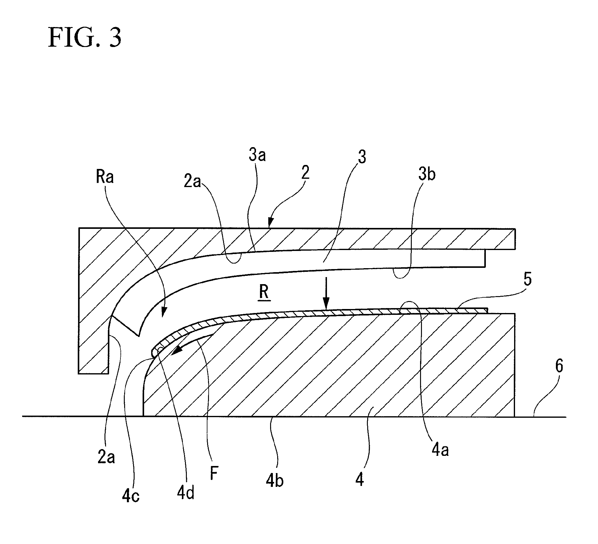
[0045]In the manufacturing method of an impeller described above, since the brazing filler metal 5 is bonded while flowing toward the inner periphery from the bond part of the blade 3 and the cover 4 during bonding, it is possible to prevent an insufficient amount of the brazing filler metal 5 from being supplied to the inner peripheral bond part end 4c. Therefore, it is possible to ensure the bonding strength at the bond part and increase the reliability of the bond part.

[0046]Next, an embodiment modified from the above-mentioned embodiment will be described with reference to the accompanying drawings. Same elements or similar elements of the above-mentioned embodiment are denoted by same reference numerals, and a detailed description thereof will be omitted. Other configurations different from those of the embodiment will be described.

[0047]The first modified embodiment illustrated in FIG. 4 is different from the manufacturing method of the above-mentioned embodiment in that a pr...

third modified embodiment

[0050]A third modified embodiment illustrated in FIG. 6 replaces the manufacturing method of the above-mentioned embodiment.

[0051]Specifically, in the manufacturing method of an impeller according to the above-mentioned embodiment, the blade 3, which is formed integrally with the disc 2 in advance, is bonded to the cover 4. However, in the third modified embodiment, a flat surface 4b of a cover 4 formed integrally with a blade 3 in advance is placed on a floor 6, and in this state, a brazing filler metal 5 is disposed on a disc-side blade edge 3a of the blade 3, and the disc 2 is disposed on and bonded to the blade 3 (the brazing filler metal 5) using the brazing filler metal 5. In addition, the position of the brazing filler metal 5 is not limited to the disc-side blade edge 3a, and the brazing filler metal 5 may be attached to the front surface 2a of the disc 2 so as to bond the blade 3 and the disc 2 to each other.

[0052]In the third modified embodiment, the cover 4 is disposed su...


PUM

PropertyMeasurementUnit
shapeaaaaaaaaaa
aerodynamic performanceaaaaaaaaaa
Raaaaaaaaaaa

Abstract

A manufacturing method of an impeller includes: forming a plurality of blades integrally on a blade attachment surface of one of a disc and a cover; placing the cover on a floor so as to face up the blade attachment surface of the cover; disposing the disc on the cover so as to face down the blade attachment surface of the disc; and bonding the plurality of blades to the blade attachment surface of the other of the disc and the cover which is not formed integrally with the plurality of blades by using a bonding material.

Description

BACKGROUND OF THE INVENTION[0001]1. Field of the Invention[0002]The present invention relates to manufacturing method of an impeller used in a centrifugal rotor such as a centrifugal compressor.[0003]Priority is claimed on Japanese Patent Application No. 2009-015451, filed on Jan. 27, 2009, the contents of which are incorporated herein by reference.[0004]2. Description of the Related Art[0005]As an impeller used for a centrifugal rotor such as a centrifugal compressor, an impeller (a closed impeller) is known to which a cover is attached, which includes a disc attached to a rotation shaft, a cover opposed to the disc so as to have a space, and a plurality of blades connecting the disc with the cover. In the cover-attached impeller, the space which is enclosed by the surfaces of the plurality of blades and surfaces of the cover and the disc which are opposed to each other, functions as a passage for compressing gas. The impeller provided in the centrifugal compressor is manufactured ...

Claims


Application Information

Patent Timeline
Patent Type & Authority Applications(United States)
IPC IPC(8): F01D5/14B23P15/04
CPCY10T29/49316B23K1/0018B23P15/006
Inventor WATANABE, YUJIROTAKATANI, HIDEAKIMIYAGAWA, KAZUYOSHIMASUMOTO, MASANORI
Owner MITSUBISHI HEAVY IND LTD
Why Eureka
Try Eureka