Ceramic joint body

a joint body and ceramic technology, applied in the field of ceramic bonded bodies, can solve the problems of insufficient corrosion resistance of the bonded part, inability to stand for use, corroded ceramic, etc., and achieve the effects of preventing warping, preventing damage of objects, and suppressing warping

Inactive Publication Date: 2005-07-26
IBIDEN CO LTD
View PDF22 Cites 30 Cited by
  • Summary
  • Abstract
  • Description
  • Claims
  • Application Information

AI Technical Summary

Benefits of technology

[0068]It is because the drop of the thermal conduction at a high temperature and occurrence of warping can be suppressed.
[0069]The cylindrical body 17 has a function of firmly supporting the ceramic substrate 11 and is capable of preventing wa

Problems solved by technology

Further, in the case of producing a bonded body by such a method, the strength of the bonded part is insufficient and the corrosion resistance of the bonded part is also insufficient and accordingly, if being exposed to reactive gases

Method used


Image

  • Ceramic joint body
  • Ceramic joint body
  • Ceramic joint body

Examples


example 1

Production of an Electrostatic Chuck (see FIGS. 4 to 6)

[0159](1) Green sheets with a thickness of 0.47 mm were obtained by forming a composition obtained by mixing 100 parts by weight of an aluminum nitride powder (produced by Tokuyama Corporation, average particle size of 1.1 μm), 4 parts by weight of Y2O3 (average particle size of 0.4 μm), 12 parts by weight of an acrylic resin-based binder, 0.5 parts by weight of a dispersant, and 53 parts by weight of alcohol consisting of 1-butanol and ethanol by a doctor blade method.

[0160](2) Next, after the green sheets were dried at 80° C. for 5 hours, the following green sheets were formed: green sheets which were not processed, the green sheets having through holes for via holes for connecting resistance heating elements and conductor circuits by punching, the green sheets having through holes for via holes for connecting conductor circuits and external terminals, and the green sheets having through holes for via holes for connecting elec...

example 2

Production of a Ceramic Heater (see FIGS. 1 to 3 and FIG. 9)

[0175](1) Green sheets with a thickness of 0.47 mm were obtained by forming a composition obtained by mixing 100 parts by weight of an aluminum nitride powder (produced by Tokuyama Corporation, average particle size of 1.1 μm), 4 parts by weight of yttrium oxide (Y2O3:yttria average particle size of 0.4 μm), 11.5 parts by weight of an acrylic resin-based binder, 0.5 parts by weight of a dispersant, and 53 parts by weight of alcohol consisting of 1-butanol and ethanol by a doctor blade method.

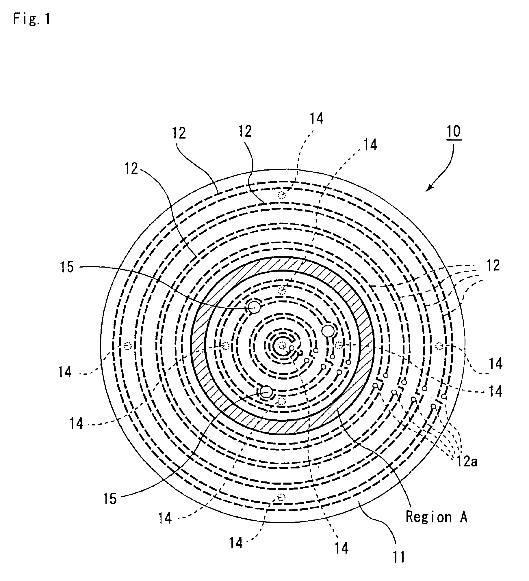
[0176](2) Next, after the green sheets were dried at 80° C. for 5 hours, portions 15 to be through holes for letting lifter pins pass through to transport a silicon wafer, portions to be via holes 630, and portions to be conductor-filled through holes 63, 63′ were formed by punching as shown FIG. 1.

[0177](3) A conductor containing paste A was produced by mixing 100 parts by weight of a tungsten carbide particle having an average particl...

example 3

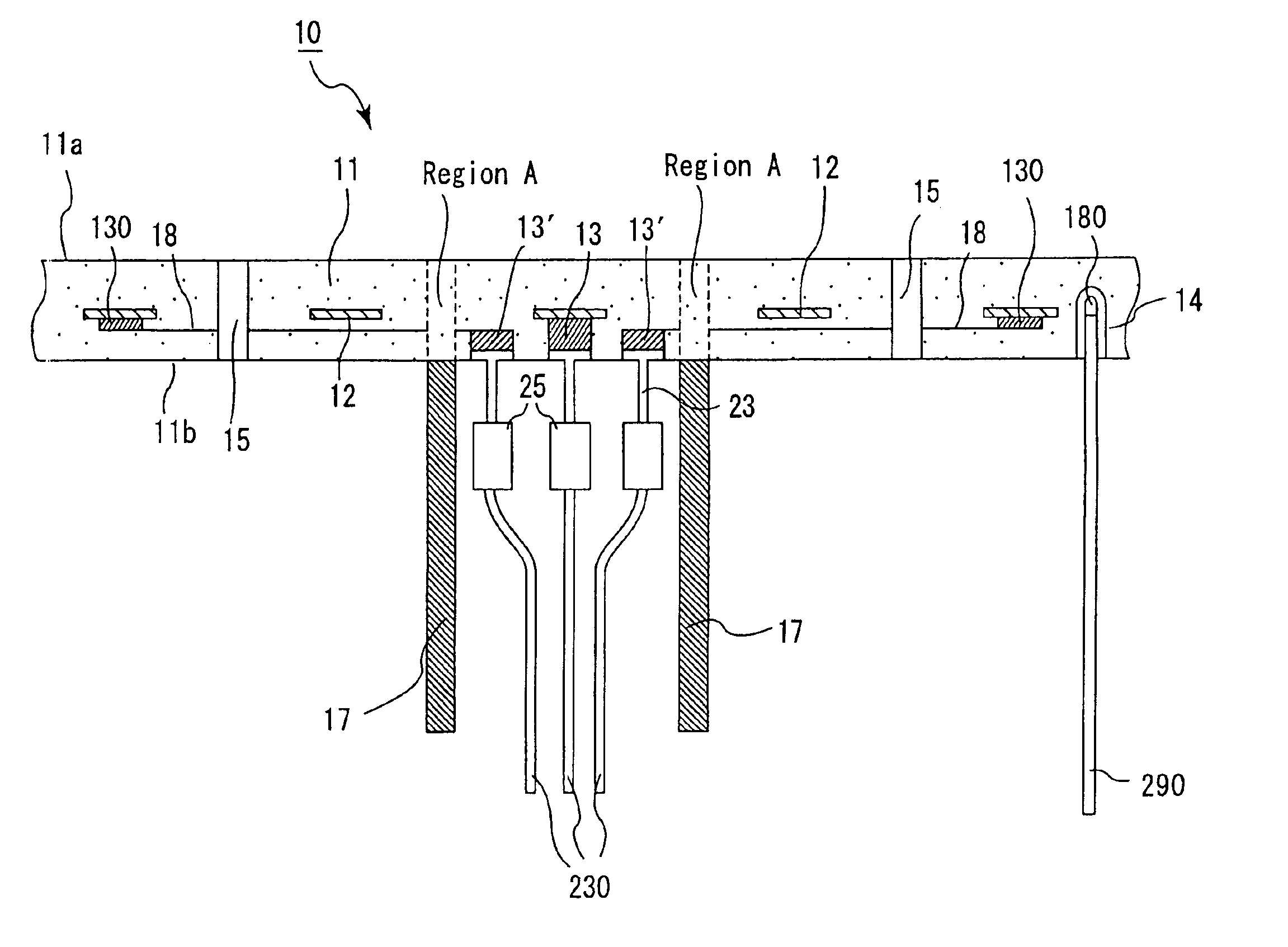
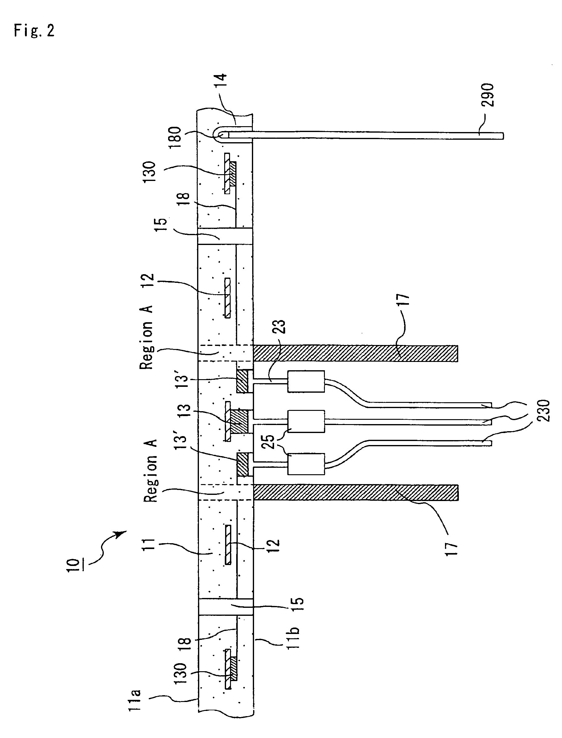
[0191]In this example, as shown in FIG. 10, a ceramic bonded body 42 was produced in the same manner as Example 1, except that patterns were formed so as to make resistance heating elements 42 exist in a large portion of the region (region A) above the bonding interface of the cylindrical body 17 and the ceramic substrate 41 (80% of the area of the bonding interface in a plan view, accordingly, the region where no resistance heating element existed was 20%). Incidentally, the resistance heating elements 42 were bonded with external terminals 23 via through holes 43 by a Ag / Ni brazing material (not illustrated).


PUM

PropertyMeasurementUnit
Fractionaaaaaaaaaa
Percent by massaaaaaaaaaa
Weightaaaaaaaaaa

Abstract

A ceramic joint body including a ceramic substrate and a ceramic body such as a cylindrical body firmly bonded to each other and excellent in corrosion resistance in the ceramic substrate for use for a semiconductor product producing/examining the step. The ceramic bonded body includes a ceramic substrate in which a conductor is provided, and a ceramic body bonded to a bottom face of the ceramic substrate. The ceramic bonded body has a region, where no conductor is formed, in at least a part of a region above a bonding interface between the ceramic substrate and the ceramic body.

Description

TECHNICAL FIELD[0001]The present invention relates to a ceramic bonded body which is used for a hot plate (a ceramic heater), an electrostatic chuck, a susceptor and the like and which comprises a ceramic substrate embedded with a conductor therein and a ceramic body such as a ceramic cylindrical body bonded to the bottom face of the substrate.BACKGROUND ART[0002]A heater, an electrostatic chuck and the like using a substrate made of a metal such as a stainless steel and an aluminum alloy have been conventionally used, as a semiconductor producing / examining device including an etching apparatus, a chemical vapor deposition apparatus and the like.[0003]However, such a heater made of a metal has the following problems.[0004]At first, since it is made of a metal, the thickness of the heater plate has to be as thick as about 15 mm. This is because, in the case of a thin metal plate, warp and strain are caused due to thermal expansion attributed to heating, so that a silicon wafer put on...

Claims


Application Information

Patent Timeline
IPC IPC(8): C04B35/10C04B35/565C04B37/00H01L21/67H01L21/00H01L21/683C04B35/581C04B35/645
CPCB32B18/00C04B35/10C04B35/5607C04B35/5626C04B35/565C04B35/581C04B35/6264C04B35/62655C04B35/63C04B35/6303C04B35/634C04B35/645C04B37/001C04B37/005H01L21/67103H01L21/6831H01L21/6833Y10T428/24926B32B2309/022B32B2311/02B32B2311/14B32B2311/22C04B2235/3201C04B2235/3203C04B2235/3206C04B2235/3217C04B2235/3225C04B2235/3821C04B2235/3865C04B2235/422C04B2235/5436C04B2235/5445C04B2235/6025C04B2235/606C04B2235/658C04B2235/721C04B2235/77C04B2235/94C04B2235/96C04B2235/963C04B2235/9669C04B2237/066C04B2237/40C04B2237/403C04B2237/405C04B2237/408C04B2237/50C04B2237/62C04B2237/68C04B2237/704Y10T428/24917B32B2038/042H01L21/68
Inventor ITO, YASUTAKAOHKURA, KAZUTERU
Owner IBIDEN CO LTD
Why Eureka
Try Eureka