Method and apparatus for cooling computer memory

a computer memory and cooling technology, applied in the field of high-power density electronics cooling methods, apparatuses and devices, can solve the problems of increasing clock frequency, power consumption and heat dissipation of system memory, and power consumption that is high enough to thermally challenge the dram components, etc., to achieve the effect of reducing laminar flow, increasing surface area, and creating turbulen

Active Publication Date: 2011-01-25
KIOXIA CORP
View PDF11 Cites 8 Cited by
  • Summary
  • Abstract
  • Description
  • Claims
  • Application Information

AI Technical Summary

Benefits of technology

[0012]In view of the above, it can be seen that the invention utilizes a coolant-containing heatpipe embedded into a primary heat spreader adapted for mounting on a memory module, such that heat is transferred transfer from chips on the module to the heatpipe. The heatpipe then extends into a secondary heat spreader, where any coolant that has vaporized as a result of heating by the chips condenses. The resultant phase change from vapor to liquid phase dissipates heat to the secondary heat spreader, from which the heat is transferred to the surrounding environment. The secondary heat spreader is preferably positioned above the primary heat spreader and the memory module, thereby creating an air channel between the primary and secondary heat spreaders. The secondary heat spreader is preferably configured to have increased surface area and create turbulence in the air channel that reduces laminar flow and promotes heat transfer to the environment.
[0013]In short, advantages of the invention can be briefly summarized to include the use of heatpipe technology to provide efficient phase change-based heat absorption from a memory module and heat release from the secondary heat spreader, good thermal contact for maximizing heat transfer from the memory module to the heatpipe through the primary heat spreader, and placement of the secondary heat spreader to maximize thermal dissipation to the environment.

Problems solved by technology

Aside from the increased footprint, the power consumption of system memory has also increased far beyond the levels found in legacy memory solutions.
Historically, only the Rambus DRAM memory technology (Rambus, Inc.) had a power consumption high enough to thermally challenge the DRAM components.
However, modern memory with increasing clock frequencies can incur power consumption and heat dissipation in excess of that found only a few years ago in commodity memory systems.
An inherent drawback of conventional memory heat spreaders is that their physical size does not exceed that of the memory module; as a result, while small hot-spots are dissipated over an increased surface, the overall dissipation area of the heat spreader is not increased compared to the module itself.
Thermal dissipation is, however, limited by the radiator surface area and the temperature delta to the environment.
However, within the confined space available for each memory module on a motherboard, passive heat conductance across a solid structure becomes the primary limitation for moving heat away from its source.
As memory modules have become more thermally challenged due to increased power consumption, the design of the memory subsystem on most motherboards has changed little to accommodate much in terms of thermal management solutions because of space constraints.
The high operating frequencies of high performance memory modules are particularly affected since the power consumption increases with frequency, and to achieve higher frequencies the voltage often must also be raised.
Higher power consumption increases the junction temperature on the memory die, which in turn slows down signal propagation along the interconnect of the memory die, thereby reducing the maximum attainable frequency of the memory and potentially increasing the error rate.
Because of the limited space between memory modules, the cross-sectional area of any heat-dissipating device must be very small, exacerbating the limitations of passive cooling techniques.
Furthermore, transferring heat to fins is similarly hampered by the same limitations of the fin design and passive conductance limitations.
However, forced water cooling is not practical for all implementations, especially since it requires a considerable amount of additional equipment, for example, radiators, tubing and pumps.

Method used


Image

  • Method and apparatus for cooling computer memory
  • Method and apparatus for cooling computer memory

Examples


Embodiment Construction

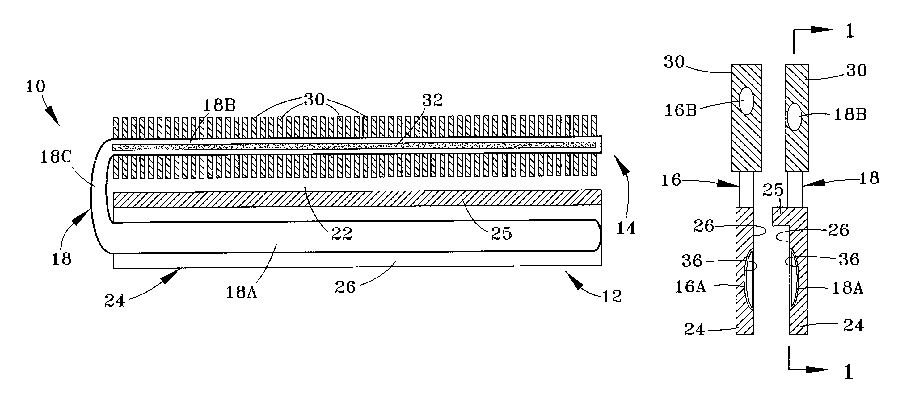
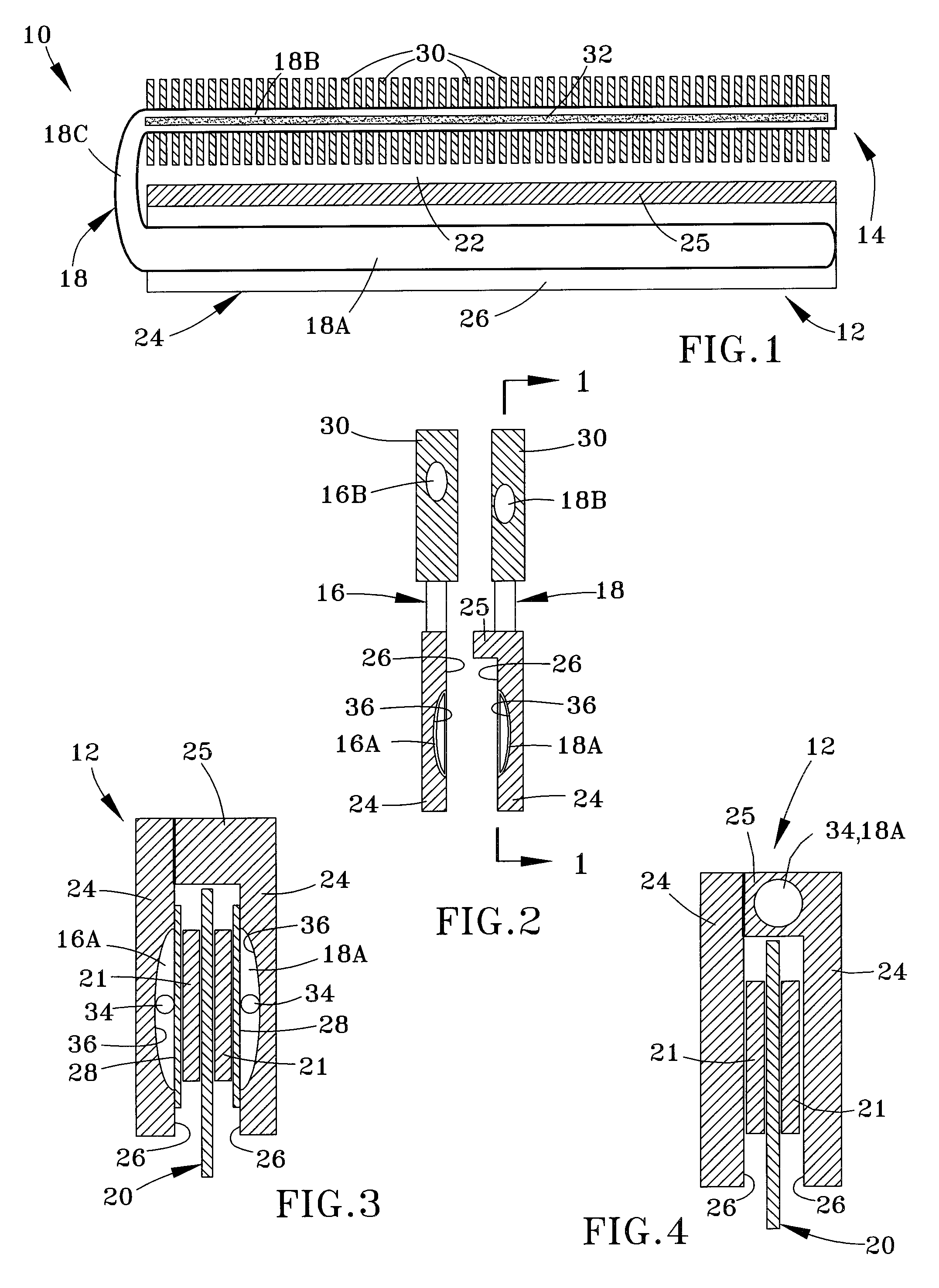
[0019]The present invention provides a thermal management solution that utilizes at least one heatpipe for cooling modules of a computer system memory. The heatpipe is directly attached to a primary heat spreader that preferably is in direct thermal contact with memory chips on a memory module to absorb heat from the chips. The heatpipe is configured to make close thermal contact with the primary heat spreader, and contains water in a partial vacuum to lower the boiling point of the water to approximately or below the maximum operating temperature identified for at least one of the memory chips, for example, based on a maximum junction temperature for the memory chips that if exceeded would slow down signal propagation along the interconnect of the memory die, thereby reducing the maximum attainable frequency of the memory and potentially increasing the error rate. Alternatively, a different coolant could be chosen whose boiling temperature is approximately the highest operating tem...


PUM


Abstract

A method and apparatus for cooling chips on a computer memory module. The apparatus includes a primary and secondary heat spreaders, at least a first heatpipe coupled to the primary heat spreader and having a remote portion spaced apart from the primary heat spreader and thermally contacting the secondary heat spreader, and a coolant within the first heatpipe and the primary heat spreader so as to absorb heat from the primary heat spreader and conduct the heat to the secondary heat spreader. The primary heat spreader has at least two panels configured to engage the memory module therebetween, with facing contact surfaces of the panels adapted for thermal contact with the module chips. The secondary heat spreader is configured to increase surface dissipation of heat from the first heatpipe into the environment. The coolant has a boiling point at or below a maximum preselected operating temperature of the module chips.

Description

CROSS REFERENCE TO RELATED APPLICATIONS[0001]This application claims the benefit of U.S. Provisional Application No. 60 / 940,155, filed May 25, 2007, the contents of which are incorporated herein by reference.BACKGROUND OF THE INVENTION[0002]The present invention generally relates to methods, apparatuses, and devices for cooling high-power density electronics, including but not limited to memory modules of computers. More particularly, this invention relates to cooling methods, apparatuses, and devices that utilize a heatpipe to cool a computer memory module.[0003]Computer memory has evolved from a small number of integrated memory chips to a multi-module subsystem. Aside from the increased footprint, the power consumption of system memory has also increased far beyond the levels found in legacy memory solutions. A prominent role in the overall power consumption of a system memory module is played by the actual mode of operation or state of the Dynamic Random Access Memory (DRAM) chi...

Claims


Application Information

Patent Timeline
Patent Type & Authority Patents(United States)
IPC IPC(8): H05K7/20H01L23/34F28F7/00
CPCF28D15/0266H01L23/427H01L2924/0002H01L2924/00
Inventor MONH, MOHASITPETERSEN, RYAN
Owner KIOXIA CORP
Why Eureka
Try Eureka