
Switching between coding schemes

a coding scheme and hybrid technology, applied in the field of hybrid coding system, can solve the problems of difficult to achieve smooth transition, generic audio coders are not able to handle speech at low bitrate, speech coders handle music segments quite poorly, etc., and achieve the effect of simplifying the overall operation of the coding system

Active Publication Date: 2011-01-25
INTELLECTUAL VENTURES I LLC
View PDF10 Cites 37 Cited by
  • Summary
  • Abstract
  • Description
  • Claims
  • Application Information

AI Technical Summary

Benefits of technology

"The invention relates to a method for smoothly transitioning between two coding schemes, particularly between a first coding scheme and a second coding scheme that is based on MDCT. The method involves using a window sequence to split the source spectrum into nearly uncorrelated spectral components, and then using these components to calculate the MDCT coefficients for the second coding scheme. The method also includes providing for each frame of the first coding scheme a sequence of windows, which are used to calculate the MDCT coefficients for the second coding scheme. The invention simplifies the switching process and reduces the complexity of the overall coding system. It also avoids the need for extrapolations and simplifies the overall operation of the coding system. The invention can be used for audio coding, such as speech and music coding."

Problems solved by technology

It is well-known, however, that speech coders handle music segments quite poorly, whereas generic audio coders are not able to handle speech at low bitrates.
In a hybrid coder, it is one of the main challenges to achieve a smooth transition between two enabled coding schemes.
A smooth transition is particularly difficult to achieve when switching from a first coder, e.g. a speech coder, to an MDCT based coder.
This will result in audible degradation at the output signal.
Such an extrapolation, however, might introduce discontinuities and artifacts especially in the case where the frame boundaries are at the onset of a transient signal segment.

Method used


Image

  • Switching between coding schemes
  • Switching between coding schemes
  • Switching between coding schemes

Examples


Embodiment Construction

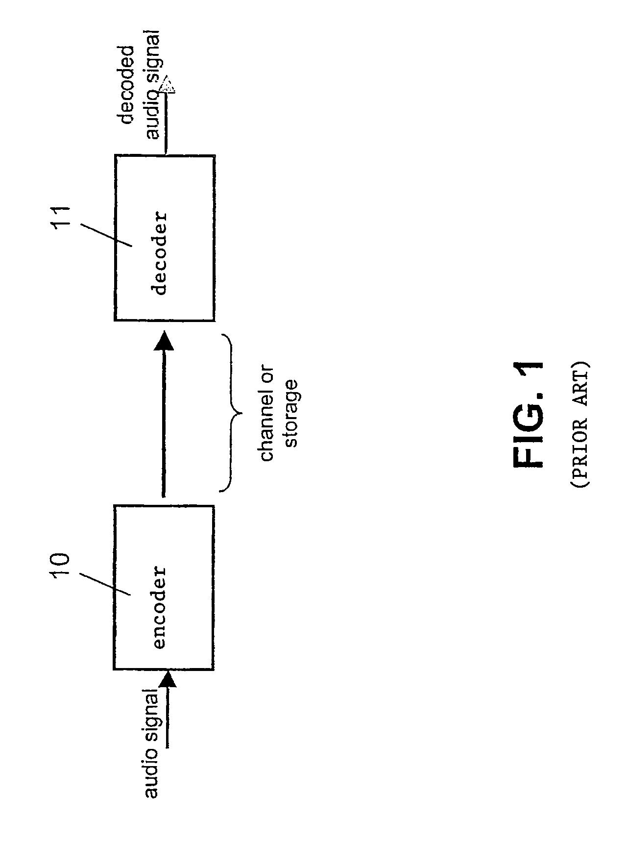
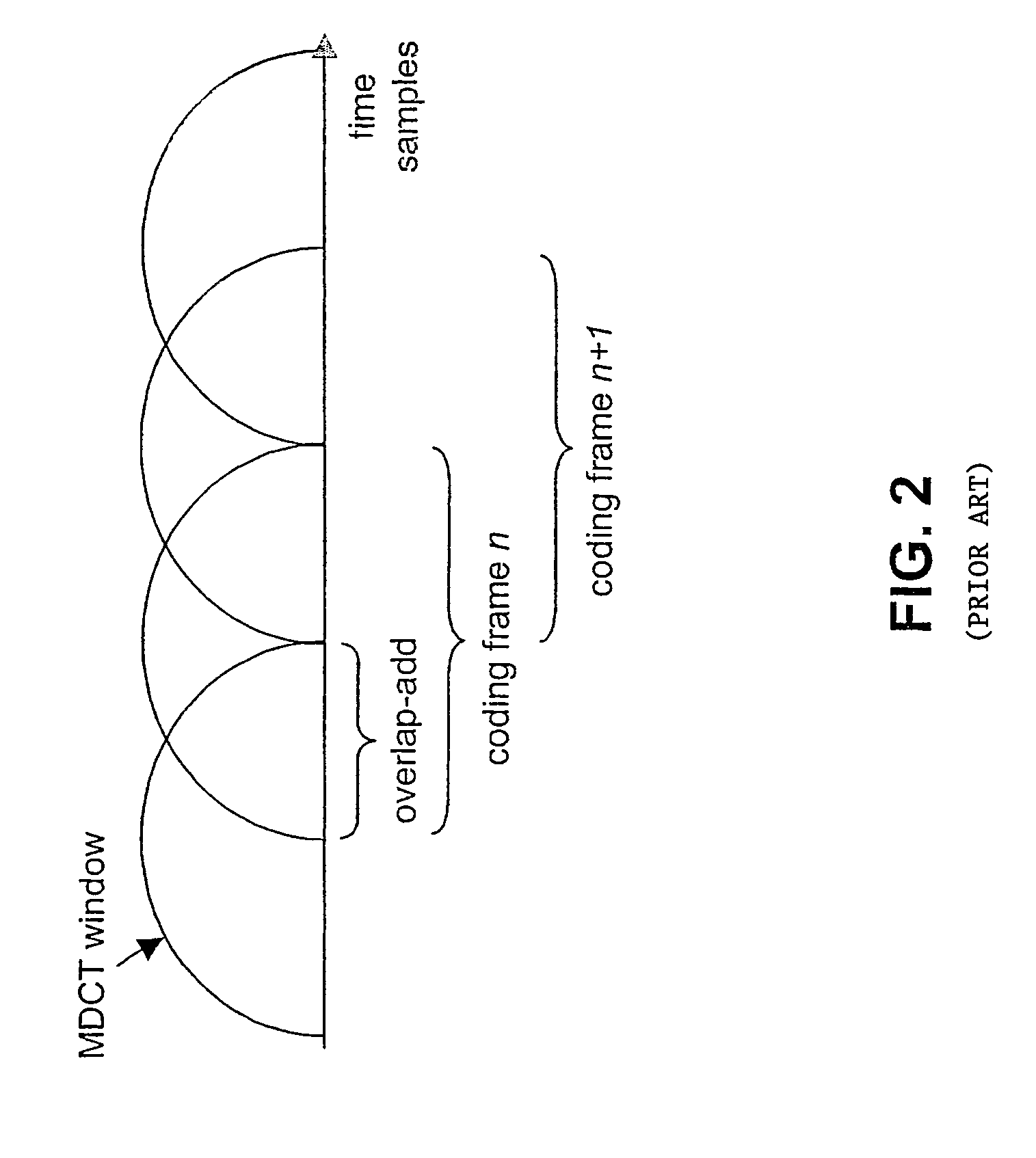
[0040]FIGS. 1 to 3 have already been described above.

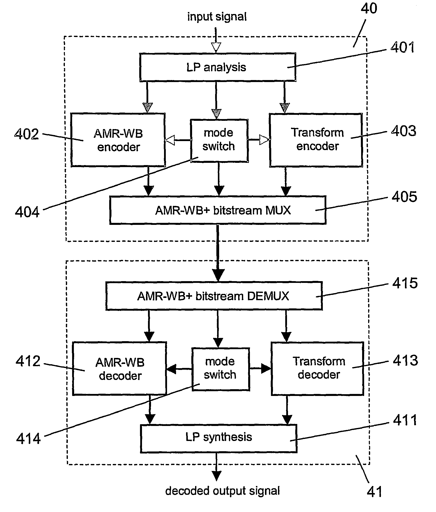
[0041]FIG. 4 presents the general structure of a hybrid audio coding system, in which the invention can be implemented. The hybrid audio coding system can be employed for transmitting speech signals with a low bitrate and music signals with a high bitrate.

[0042]The hybrid audio coding system of FIG. 4 comprises to this end a hybrid encoder 40 and a hybrid decoder 41. The hybrid encoder 40 encodes audio signals and transmits them to the hybrid decoder 41, while the hybrid decoder 41 receives the encoded signals, decodes them and makes them available again as audio signals. Alternatively, the encoded audio signals could also be provided by the hybrid encoder 40 for storage in a storing unit, from which they could then be retrieved again by the hybrid decoder 41.

[0043]The hybrid encoder 40 comprises an LP analysis portion 401, which is connected to an AMR-WB encoder 402, to a transform encoder 403 and to a mode switch 404. The mode s...


PUM


Abstract

Methods and units are shown for supporting a switching from a first coding scheme to a Modified Discrete Cosine Transform (MDCT) based coding scheme calculating a forward or inverse MDCT with a window (h(n)) of a first type for a respective coding frame, which satisfies constraints of perfect reconstruction. To avoid discontinuities during the switching, it is proposed that for a transient frame immediately after a switching, a sequence of windows (h0(n),h1(n),h2(n)) is provided for the forward and the inverse MDCTs. The windows of the window sequence are shorter than windows of the first type. The window sequence splits the spectrum of a respective first coding frame into nearly uncorrelated spectral components when used as basis for forward MDCTs, and the second half of the last window (h2(n)) of the sequence of windows is identical to the second half of a window of the first type.

Description

CROSS-REFERENCE TO RELATED APPLICATION[0001]This is the U.S. National Stage of International Application No. PCT / IB2003 / 000884 filed Mar. 11, 2003 and published in English on Sep. 23, 2004 under International Publication No. WO 2004 / 082288 A1.FIELD OF THE INVENTION[0002]The invention relates to a hybrid coding system. The invention relates more specifically to methods for supporting a switching from a first coding scheme to a second coding scheme at an encoding end and a decoding end of a hybrid coding system, the second coding scheme being a Modified Discrete Cosine Transform based coding scheme. The invention relates equally to a corresponding hybrid encoder, to a transform encoder for such a hybrid encoder, to a corresponding hybrid decoder, to a transform decoder for such a hybrid decoder, and to a corresponding hybrid coding system.BACKGROUND OF THE INVENTION[0003]Coding systems are known from the state of the art. They can be used for instance for coding audio or video signals...

Claims


Application Information

Patent Timeline
Patent Type & Authority Patents(United States)
IPC IPC(8): G06K9/36H04N7/12G10L19/02G10L19/022G10L19/18G10L19/22H04N7/24
CPCG10L19/022G10L19/18G10L19/22
Inventor OJANPERA, JUHA
Owner INTELLECTUAL VENTURES I LLC
Learn More