Torque reserve and emission control system for coordinated torque control

a technology of torque reserve and emission control system, applied in the direction of electric control, machines/engines, instruments, etc., can solve the problems of limited coordinate engine torque control, slow response time of traditional engine control system to received control signals, and limited accuracy of engine torque output control

Inactive Publication Date: 2011-02-01
GM GLOBAL TECH OPERATIONS LLC
View PDF6 Cites 11 Cited by
  • Summary
  • Abstract
  • Description
  • Claims
  • Application Information

AI Technical Summary

Problems solved by technology

Traditional engine control systems are limited in accurately controlling engine torque output.
The traditional engine control systems are also slow to respond to received control signals and limited in coordinate engine torque control with respect to various devices that affect engine torque output.
As vehicle powertrain systems include more modules and more actuators that affect torque, the architecture of the prior art becomes cumbersome to maintain and undesirably difficult to troubleshoot.
Integrating the hybrid vehicle powertrain to existing torque-modifying modules can be undesirably cumbersome with traditional powertrain control architectures.

Method used


Image

  • Torque reserve and emission control system for coordinated torque control
  • Torque reserve and emission control system for coordinated torque control
  • Torque reserve and emission control system for coordinated torque control

Examples


Embodiment Construction

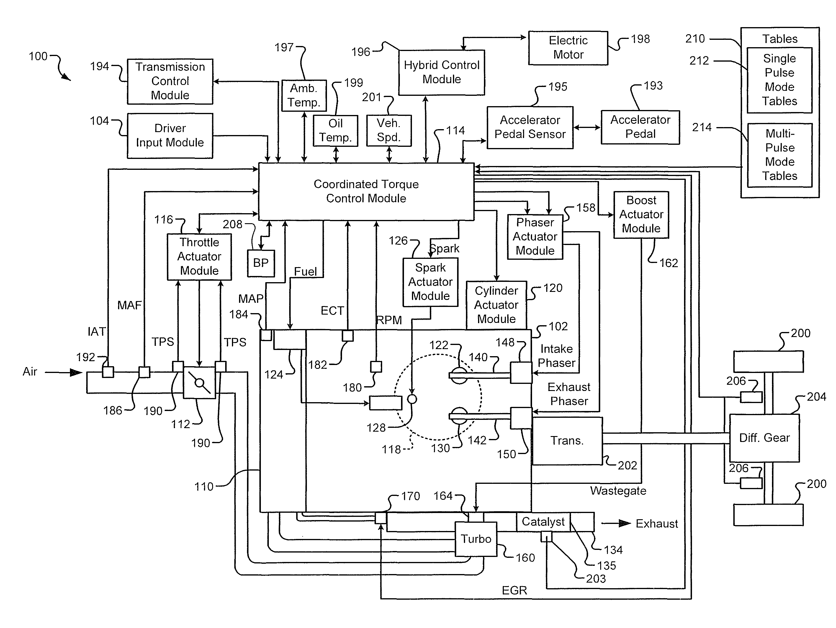
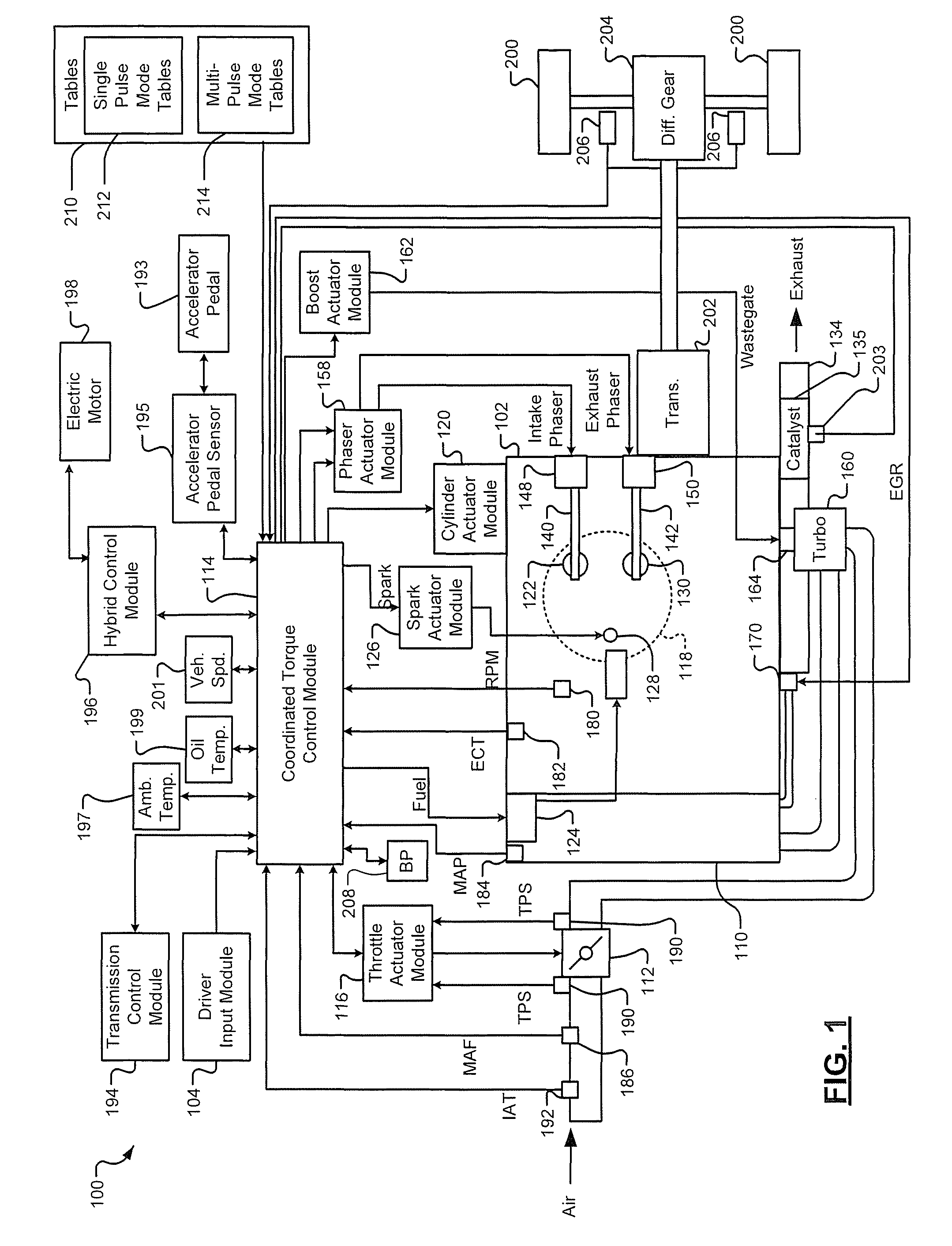
[0021]In the following description, different fuel injection pulse modes are described. Transitions between the fuel injection pulse modes may be performed based on performance of a catalyst light off (CLO). Catalyst light off refers to the quick heating of a catalyst of an exhaust system. A catalyst has an associated temperature operating range in which the catalyst is effective in reducing tailpipe hydrocarbon, carbon monoxide, and oxides of nitrogen emissions. By quickly heating the catalyst up to a temperature within the temperature operating range, tailpipe emissions are minimized.

[0022]A first fuel injection pulse mode, referred to as a single pulse mode, includes the injecting of a single pulse of fuel into a combustion chamber during a combustion cycle. A combustion cycle may, for example, in a 4-stroke engine, refer to a single sequencing through the 4 strokes (intake, compression, ignition, and exhaust). A single pulse mode may be used when an engine is not requiring maxim...


PUM


Abstract

A coordinated torque control system includes a catalyst module that generates a multi-mode enable signal based on a catalyst light off enable signal. A torque reserve module generates a torque reserve signal based on the multi-mode enable signal, an engine speed signal and an air per cylinder signal. The torque reserve module operates in a multi-pulse mode that is associated with injecting N pulses of fuel into a combustion chamber during a combustion cycle of the engine based on the multi-mode enable signal. N is an integer greater than or equal to 2.

Description

CROSS-REFERENCE TO RELATED APPLICATIONS[0001]This application claims the benefit of U.S. Provisional Application No. 61 / 171,535, filed on Apr. 22, 2009. The disclosures of the above application is incorporated herein by reference in its entirety.[0002]This application is related to U.S. Provisional Application No. 61 / 190,471, filed on Aug. 28, 2008 and U.S. Provisional Application No. 61 / 173,785, filed on Apr. 29, 2009.FIELD OF THE INVENTION[0003]The present invention relates to engine control systems and more particularly to coordinated torque control based techniques for multi-pulse direct injection operation.BACKGROUND OF THE INVENTION[0004]The statements in this section merely provide background information related to the present disclosure and may not constitute prior art.[0005]Traditional engine control systems are limited in accurately controlling engine torque output. The traditional engine control systems are also slow to respond to received control signals and limited in c...

Claims


Application Information

Patent Timeline
Patent Type & Authority Patents(United States)
IPC IPC(8): F02P5/00F02P1/00
CPCF02D11/105F02D41/024F02D41/3023F02D41/402F02D41/3064F02D2041/001F02D2250/18F02D2250/22F02D2250/26Y02T10/44Y02T10/26Y02T10/12Y02T10/40
Inventor LIVSHIZ, MICHAELKAISER, JEFFREY M.GRAHAM, CHRISTOPHER R.WHITNEY, CHRISTOPHER E.SEMRAU, ROBERT FRANCISFRANCIS, BRIAN D.
Owner GM GLOBAL TECH OPERATIONS LLC
Why Eureka
Try Eureka