Antennas with polarization diversity

a technology of polarized antennas and antennas, applied in the field of wireless communication, can solve the problems of general inconsequential orientation of antennas, and achieve the effects of preserving energy, improving signal quality, and long rang

Active Publication Date: 2011-02-01
ARRIS ENTERPRISES LLC
View PDF234 Cites 42 Cited by
  • Summary
  • Abstract
  • Description
  • Claims
  • Application Information

AI Technical Summary

Benefits of technology

[0010]With these principles in mind, embodiments of the present invention allow for the use of both vertically and horizontally polarized antenna arrays. The horizontally polarized antenna arrays of the present invention allow for the efficient distribution of RF energy into a communications environment through, for example, selectable antenna elements, reflectors and / or directors that create and influence a particular radiation pattern (e.g., a substantially omnidirectional radiation pattern). In conjunction with the vertically polarized array, a particular high-gain wireless environment may be created such that one wireless environment does not interfere with other nearby wireless environments (e.g., between floors of an office building) and, further, avoids interference created by the other environments.
[0013]Some embodiments of the present invention may implement a series a parasitic elements on an antenna array in the system. At least two of the elements may be selectively coupled to one another by a switching network. Through the selective coupling of the parasitic elements, the elements may collectively operate as a reflector or a director, whereas prior to the coupling the elements may have been effectively invisible to an emitted radiation pattern. By collectively operating as, for example, a reflector, a radiation pattern emitted by the driven elements of an array may be influenced through the reflection back of the pattern in a particular direction thereby increasing the gain of the pattern in that direction.

Problems solved by technology

Low-gain antennas have shorter range but antenna orientation is generally inconsequential.

Method used


Image

  • Antennas with polarization diversity
  • Antennas with polarization diversity
  • Antennas with polarization diversity

Examples


Embodiment Construction

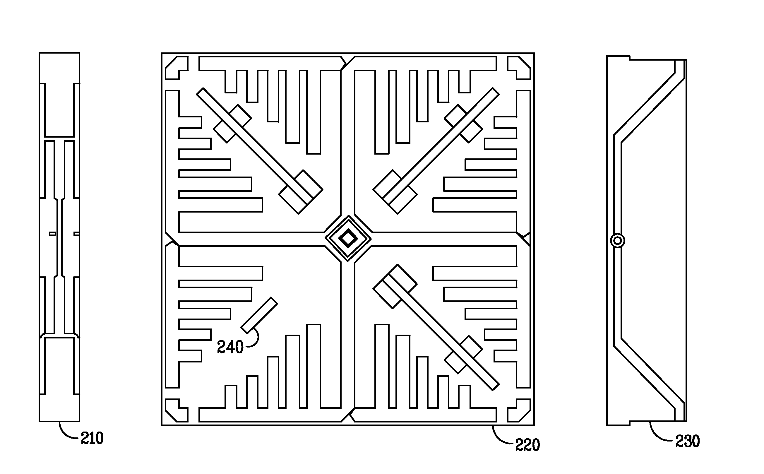
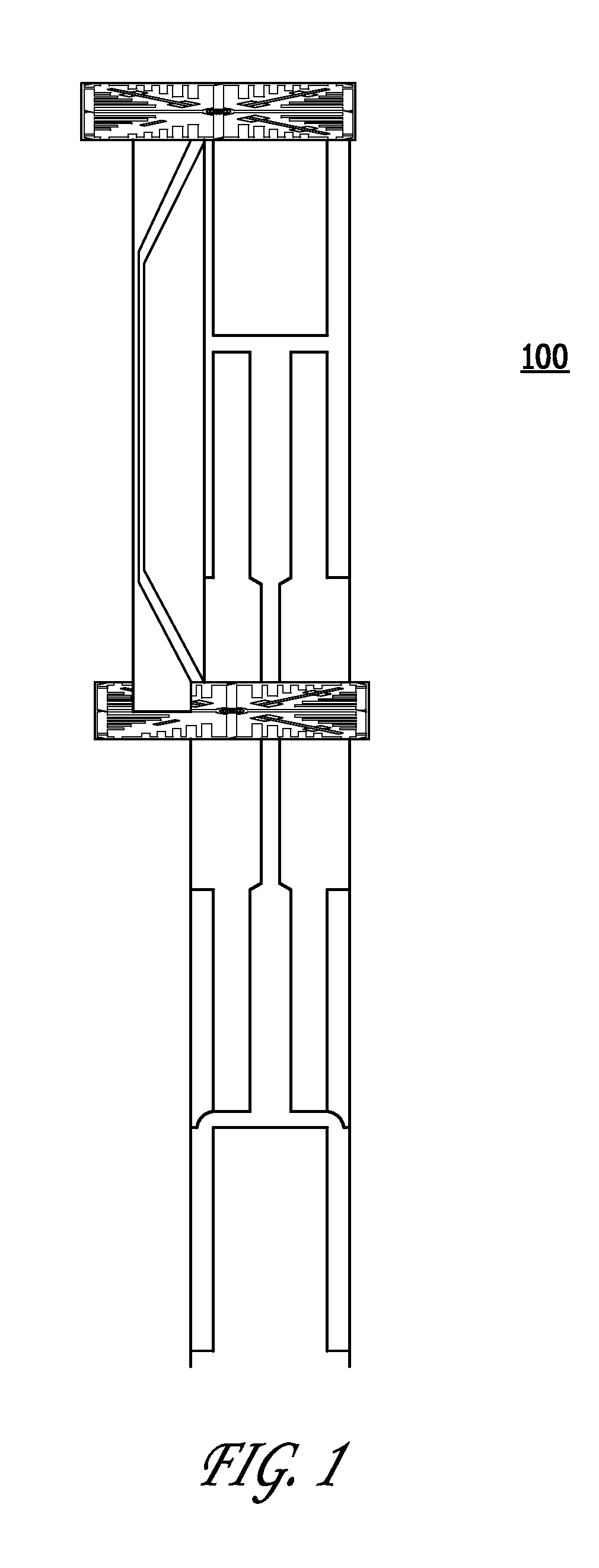
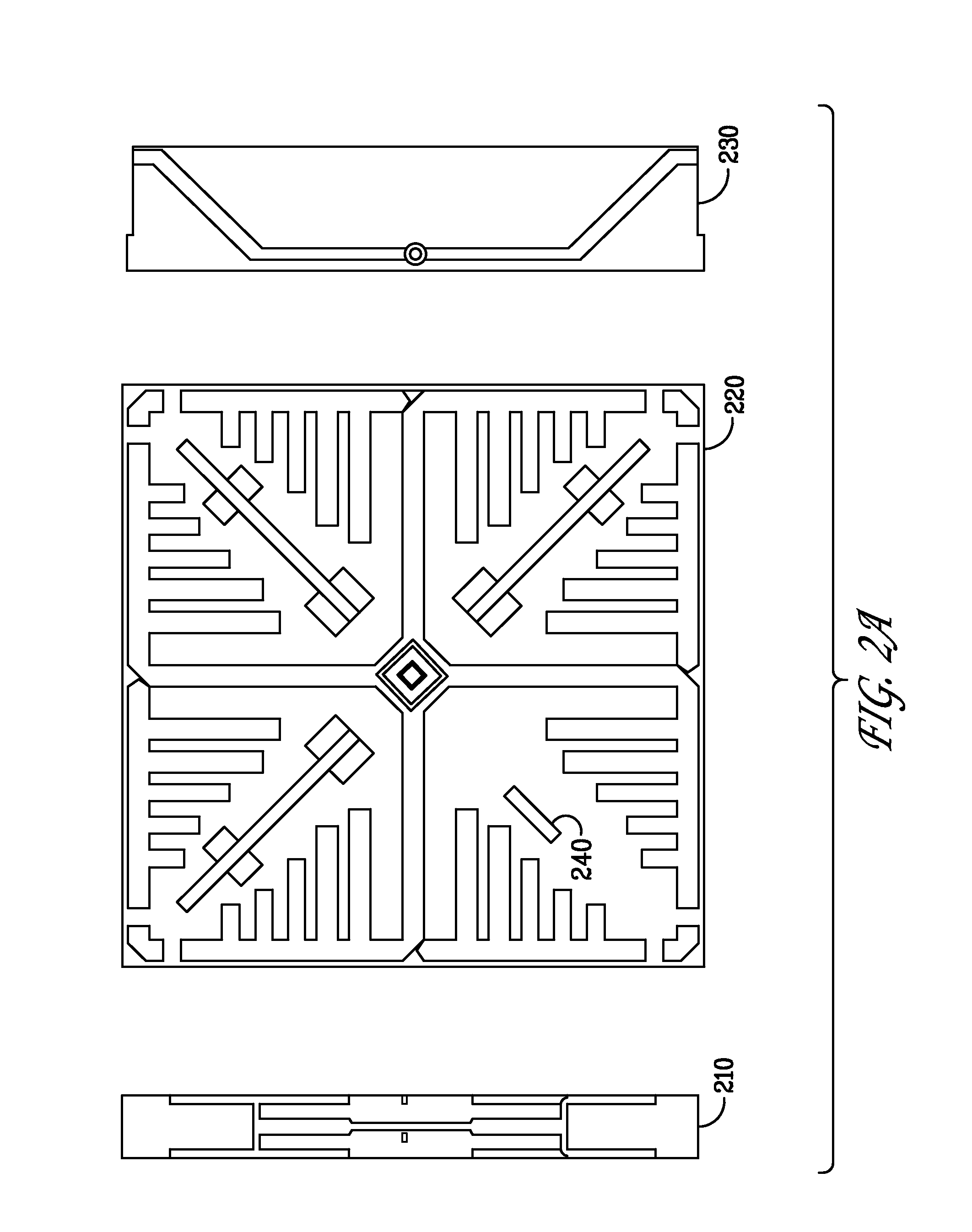
[0033]FIG. 1 illustrates an exemplary dual polarized, high-gain, omnidirectional antenna system 100 in accordance with an embodiment of the present invention. Any reference to the presently disclosed antenna systems being coaxial in nature should not be interpreted (exclusively) as an antenna element consisting of a hollow conducting tube through which a coaxial cable is passed. In certain embodiments of the antenna systems disclosed herein (such as antenna system 100), two horizontal antenna arrays sharing a common axis including a vertical antenna array are disclosed. Such systems are coaxial to the extent that those horizontal arrays share the aforementioned common vertical axis formed by the vertical array although other configurations are envisioned. Notwithstanding, various cabling mechanisms may be used with respect to a communications device implementing the presently disclosed dual polarized, high-gain, omnidirectional antenna system 100 including a coaxial feed.

[0034]While...


PUM


Abstract

A horizontally polarized antenna array allows for the efficient distribution of RF energy into a communications environment through selectable antenna elements and redirectors that create a particular radiation pattern such as a substantially omnidirectional radiation pattern. In conjunction with a vertically polarized array, a particular high-gain wireless environment may be created such that one environment does not interfere with other nearby wireless environments and avoids interference created by those other environments. Lower gain patterns may also be created by using particular configurations of a horizontal and / or vertical antenna array. In a preferred embodiment, the antenna systems disclosed herein are utilized in a multiple-input, multiple-output (MIMO) wireless environment.

Description

CROSS-REFERENCE TO RELATED APPLICATIONS[0001]The present application is a continuation and claims the priority benefit of U.S. patent application Ser. No. 11 / 646,136 filed Dec. 26, 2006 now U.S. Pat. No. 7,498,996 and entitled “Antennas with Polarization Diversity,” which is a continuation-in-part of U.S. patent application Ser. No. 11 / 041,145 filed Jan. 21, 2005 now U.S. Pat. No. 7,362,280 and entitled “System and Method for a Minimized Antenna Apparatus with Selectable Elements,” which claims the priority benefit of U.S. provisional patent application No. 60 / 602,711 filed Aug. 18, 2004 and entitled “Planar Antenna Apparatus for Isotropic Coverage and QoS Optimization in Wireless Networks” and U.S. provisional patent application No. 60 / 603,157 filed Aug. 18, 2004 and entitled “Software for Controlling a Planar Antenna Apparatus for Isotropic Coverage and QoS Optimization in Wireless Networks”; U.S. patent application Ser. No. 11 / 646,136 also claims the priority benefit of U.S. prov...

Claims


Application Information

Patent Timeline
Patent Type & Authority Patents(United States)
IPC IPC(8): H01Q9/28H01Q21/00
CPCH01Q9/285H01Q15/148H01Q21/24H01Q21/062H01Q21/205H01Q19/24H01Q3/24
Inventor SHTROM, VICTORKISH, WILLIAMBARRON, BERNARD
Owner ARRIS ENTERPRISES LLC
Why Eureka
Try Eureka