[0005]The object of the invention is therefore to provide an apparatus as mentioned at the outset which is more cost-effective.
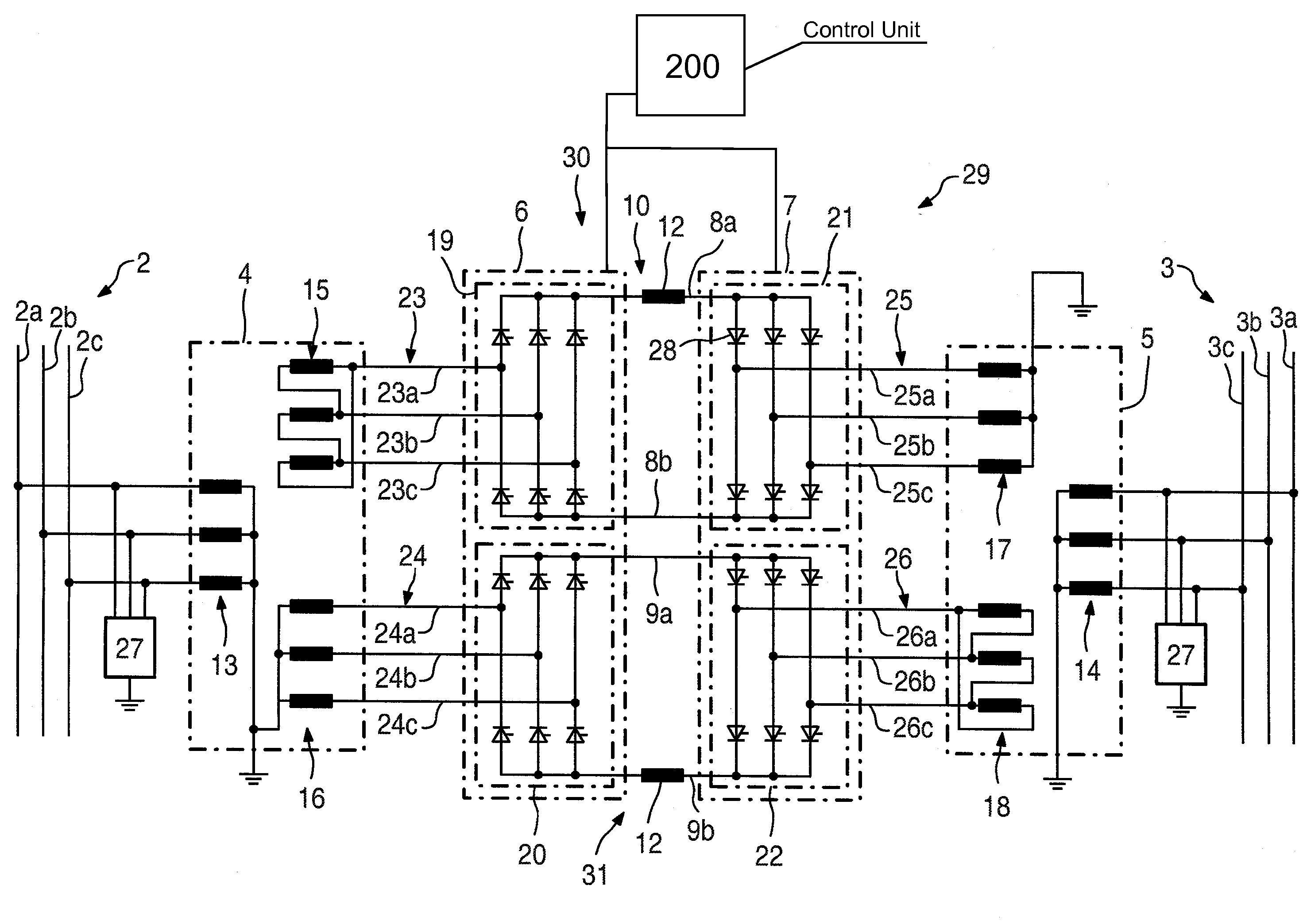
[0007]According to the invention, the converters, which are each associated with one AC voltage
system, are connected to one another on the DC side via a plurality of DC circuits. This firstly has the
disadvantage that the six-pulse current converters need to be connected to one another via additional
DC voltage lines. However, the connection via separate
DC voltage circuits allows for a broader design possibility when
coupling the converters to the respectively associated AC voltage
system. In other words, the design possibility of the inductances via which the converters can be connected to the respectively associated AC voltage system is broadened, with the result that, by expediently designing the inductances, their costs are reduced considerably. In this case, each
DC circuit has an electromagnetic, i.e. inductive or capacitive,
coupling for DC isolation of the AC voltage systems which are connected to one another. Owing to the DC isolation, the transmission of radiofrequency disturbances from one AC voltage system to the other is avoided. Complex additional filters, which are described, for example, in U.S. Pat. No. 5,414,612, can be avoided according to the invention, with the result that costs can also be saved in this way. According to the invention, twelve-pulse converters are also used, 12 initiating pulses for triggering the current converter valves being produced in one period of the AC voltage applied. As has already been mentioned in connection with the prior art, during twelve-pulse conversion the 5th and 7th
harmonics of the current are canceled out which can only be eliminated in the case of six-pulse converters by an increased complexity in terms of the filtering of the AC voltage. Furthermore, higher powers can be transmitted between the AC voltage systems by twelve-pulse current converters.
[0008]Advantageously, a first
DC circuit and the inductances connected to it are designed to be symmetrical with respect to the second
DC circuit and the inductances connected to it. Owing to a symmetrical design of the arrangements, which comprise a DC circuit and the inductances associated with it, additional means when combining the powers transmitted via different DC circuits are now superfluous, with the result that additional costs are avoided.
[0013]Advantageously, the six-pulse current converter bridge of a first converter, which six-pulse current converter bridge is connected to the secondary winding of a first
transformer whose phases are star-connected to one another, is connected on the DC side to a six-pulse current converter bridge of a second converter, which is connected on the AC side to a secondary winding of a second
transformer, whose phases are
delta-connected to one another. This wiring arrangement of the apparatus allows for the exclusive use of transformers as inductances, at the same time a symmetrical design of the DC circuits with the secondary windings associated with them of the transformers being made possible. In this case, the symmetry is produced by virtue of the fact that the phases of one six-pulse current converter bridge of the first converter are
delta-connected to one another, while the other secondary winding of the same
transformer is connected to the other six-pulse current converter bridge of the first converter. The six-pulse current converter bridge whose phases are
delta-connected is connected on the DC side to one of the six-pulse current converter bridges, which is connected to a secondary winding of another transformer, whose phases are star-connected. The six-pulse current converter bridge of the first converter, which is connected to a secondary winding of the first transformer, whose phases are star-connected to one another, is, on the other hand, connected on the DC side to a six-pulse current converter bridge, which is DC-connected to a secondary winding of the second transformer, whose phases are delta-connected. In this case, the secondary windings forming the star point are each grounded. As has already been mentioned, it is conventional, in particular in the case of high powers to be transmitted, to design the HVDC transformers to be single-phase. The single-phase transformers therefore generally have three bushings for connecting high-voltage overhead lines. The wiring of the phases takes place outside the transformer housing. In the case of grounding of the star point, this acts for each phase on at least one of the bushings of the single-phase transformers. These bushings can be designed to be considerably more cost-effective owing to the ground potential applied.
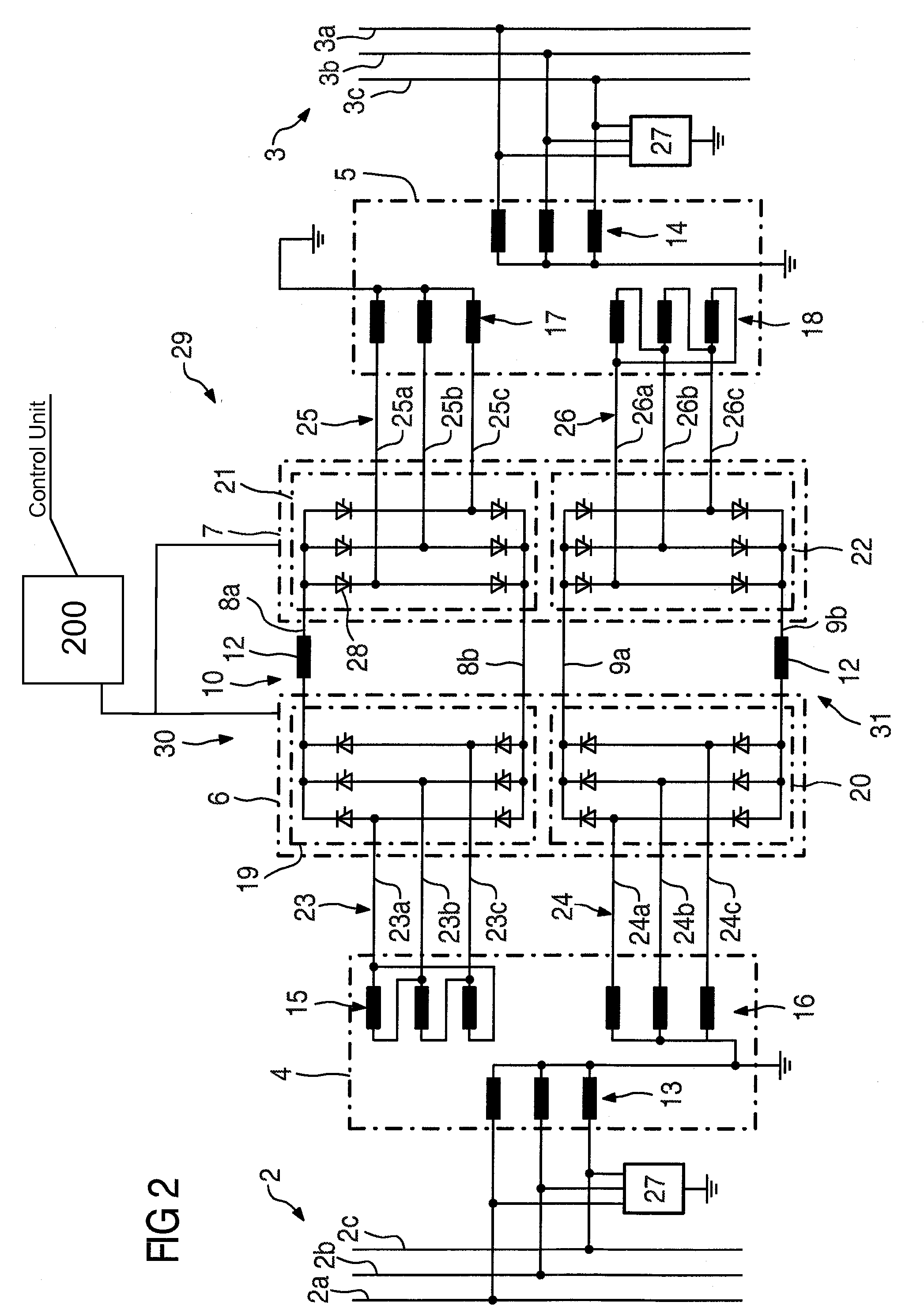
[0014]In accordance with an exemplary embodiment which deviates from this, the inductances associated with a converter each comprise a transformer and a number of
inductor coils which is dependent on the number of phases of the associated AC voltage system, it being possible for a first six-pulse current converter bridge of a first converter to be connected via first
inductor coils and for a second six-pulse current converter bridge of the first converter to be connected via a first transformer to a first AC voltage system, and the phases of a primary winding of the first transformer being star-connected to one another with grounding and the phases of its secondary winding being delta-connected. In accordance with this exemplary embodiment, a transformer which has two secondary windings with different wiring of the phases is not used for reasons of cost. Instead, a conventional transformer having a primary winding and a secondary winding is used. The primary winding is DC-connected to the associated AC voltage system during operation of the apparatus according to the invention, the primary winding having a grounded star point. The secondary winding of this transformer is connected to a first six-pulse current converter bridge of the first converter. The second six-pulse current converter bridge of this converter, on the other hand, is DC-connected to the AC voltage system via
inductor coils, a reference point for the potential of the DC voltage circuit in which the second six-pulse current converter bridge of the first converter is arranged being provided via the grounding of the primary winding of the transformer via the DC connection of the second converter bridge. A transformer having only one secondary winding and the use of inductor coils instead of a transformer having two or more secondary windings and different wiring is substantially more cost-effective and therefore has an effect on the efficiency of the entire apparatus.
[0016]In an expedient development in this regard, each inductor coil is connected in each case to a tap of a phase of the grounded primary winding of the associated transformer. Instead of being DC-connected directly to the phases of the associated AC voltage system, the inductor coils and therefore the associated six-pulse current converter bridge are connected to a tap of the polyphase primary winding. The primary winding has, for example, a three-phase design and has for each phase one tap of the winding, for example in the center. The tap is passed to the outside from the transformer and can then be DC-connected to the inductor coils. The connection of the apparatus to the AC voltage system therefore has a simplified and more cost-effective design.

