Method for determining a route distance value

a distance value and route technology, applied in the field of route distance value determination, can solve the problems of not determining the optimal path, requiring more time than initial transmission,

Inactive Publication Date: 2011-02-01
SIEMENS AG
View PDF7 Cites 3 Cited by
  • Summary
  • Abstract
  • Description
  • Claims
  • Application Information

AI Technical Summary

Benefits of technology

The inventors propose a method for determining a path distance value for a path, in which the path distance value is determined on the basis of a first probability. The first probability indicates the probability that during a transmission along the path, a data packet must be transmitted several times at at least one link of the path. This means that the first probability states the probability that a retransmission is necessary at at least one link. The metric determined by the method has the advantage of facilitating an improved path selection for time-critical data transmissions.
In an advantageous embodiment the number of links of the path is additionally taken into consideration during the determination of the path distance value. This offers the advantage that shorter paths are preferred to longer paths.

Problems solved by technology

However, retransmissions have the disadvantage that they can require more time than initial transmissions.
Therefore, for certain types of data transmission in specific scenarios, the disadvantage of ETX is that it does not determine the optimal path.

Method used


Image

  • Method for determining a route distance value
  • Method for determining a route distance value
  • Method for determining a route distance value

Examples


Embodiment Construction

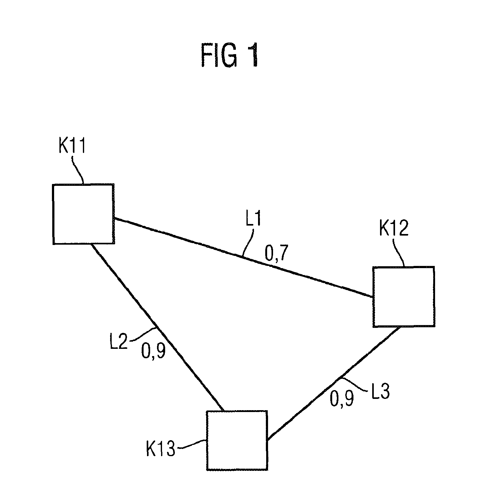
Reference will now be made in detail to the preferred embodiments of the present invention, examples of which are illustrated in the accompanying drawings, wherein like reference numerals refer to like elements throughout. FIG. 1 shows an exemplary network section including an eleventh to a thirteenth node K11 . . . 13. Furthermore, FIG. 1 shows a first link L1 between the eleventh node K11 and the twelfth node K12, a second link L2 between the eleventh node K11 and the thirteenth node K13, and a third link L3 between the twelfth node K12 and the thirteenth node K13. The first link L1 has a link metric of 0.7, whereas the second link L2 and third link L3 each have a link metric of 0.9.

In this exemplary network section, a data transmission from the eleventh node K1 to the twelfth node K2 take place via two possible paths. The first path includes the first link L1. The second path includes the second link L2 and the third link L3. The first path thus runs directly from the eleventh no...


PUM


Abstract

A method determines a route in distance value for use in routing protocols. An optimum route is determined for time-critical transmissions such as videotelephony or VoIP. For this purpose, the route distance value is calculated as the product of the link metrics for the links of a route, said link metrics being the product of data packet arrival rates. This value is the optimum value for the route which requires the lowest number of repeated packet transmissions (retransmissions). Optionally, an additional factor can be inserted in the link metrics, which factor ensures that the length of a route is also taken into consideration.

Description

CROSS REFERENCE TO RELATED APPLICATIONSThis application is based on and hereby claims priority to German Application No. 10 2006 014 910.6 filed on Mar. 30, 2006 and PCT Application No. PCT / EP2007 / 050781 filed on Jan. 26, 2007, the contents of which are hereby incorporated by reference.BACKGROUND OF THE INVENTIONA network facilitates the transmission of messages between its nodes. In a network not all nodes of the network are directly connected to all other nodes. A message from one transmitting node to a receiving node therefore frequently has to be forwarded via one or several intermediate nodes in order to reach the receiving node from the transmitting node. In this case the route from the transmitting node via the intermediate nodes to the receiving node is described as the path or route.In order to select a suitable path for a message from a large number of theoretically possible paths in a network, a routing method is used. Firstly, the routing method determines at least one, ...

Claims


Application Information

Patent Timeline
Patent Type & Authority Patents(United States)
IPC IPC(8): G01R31/08
CPCH04L45/12H04L45/123
Inventor KUTSCHENREUTER, MATTHIASSCHWINGENSCHLOGL, CHRISTIAN
Owner SIEMENS AG
Why Eureka
Try Eureka