
Security cover for a utility pole and enclosure and method

a technology for enclosures and utility poles, applied in the direction of insulating bodies, screws, lighting and heating apparatuses, etc., can solve the problems of explosion in the frequency of theft of copper wiring from utility poles and related junction boxes and conduits, damage to fixtures, wiring, fixtures,

Inactive Publication Date: 2011-02-08
LIGHTING SECURITY PRODS
View PDF10 Cites 22 Cited by
  • Summary
  • Abstract
  • Description
  • Claims
  • Application Information

AI Technical Summary

Benefits of technology

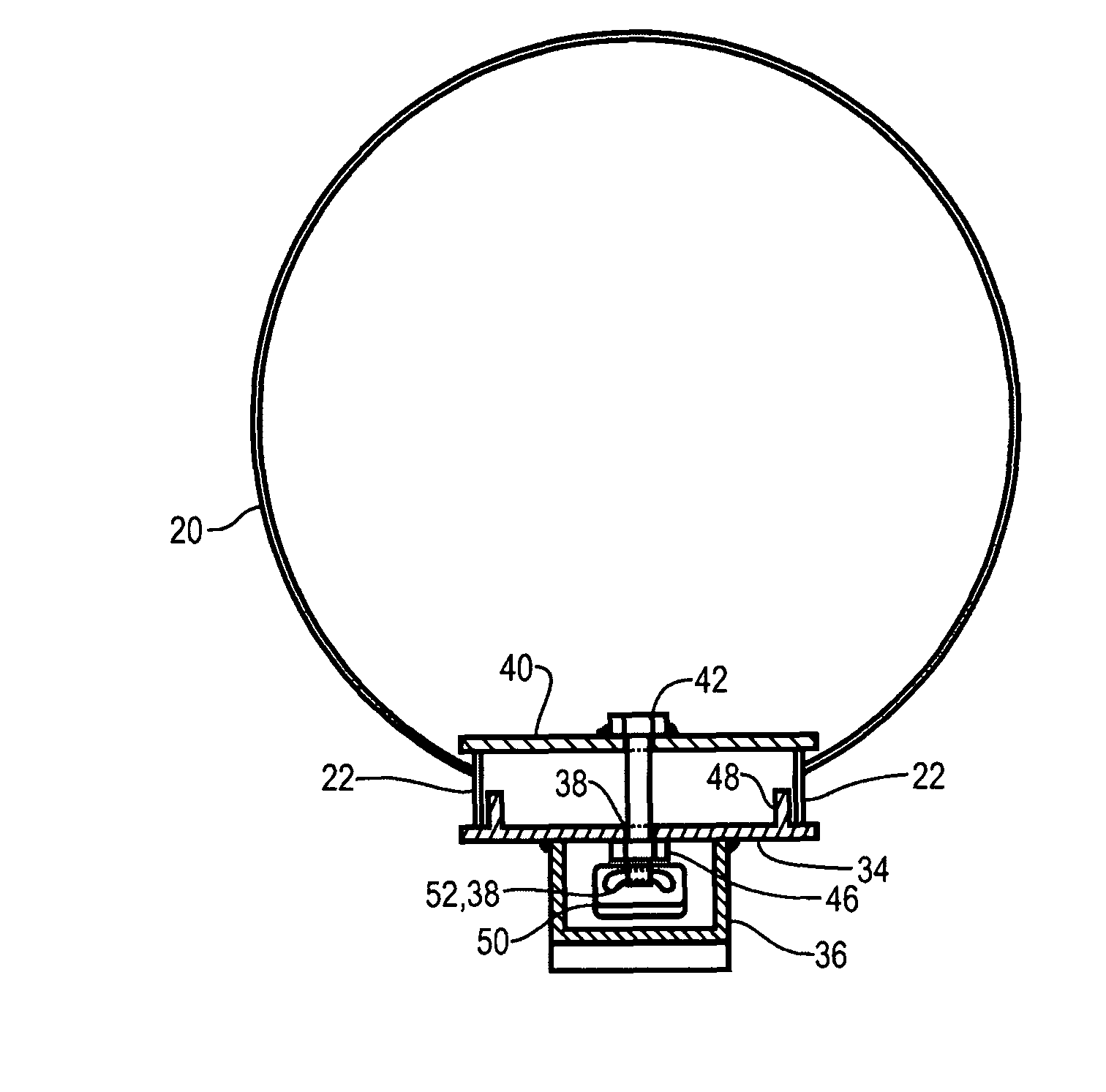
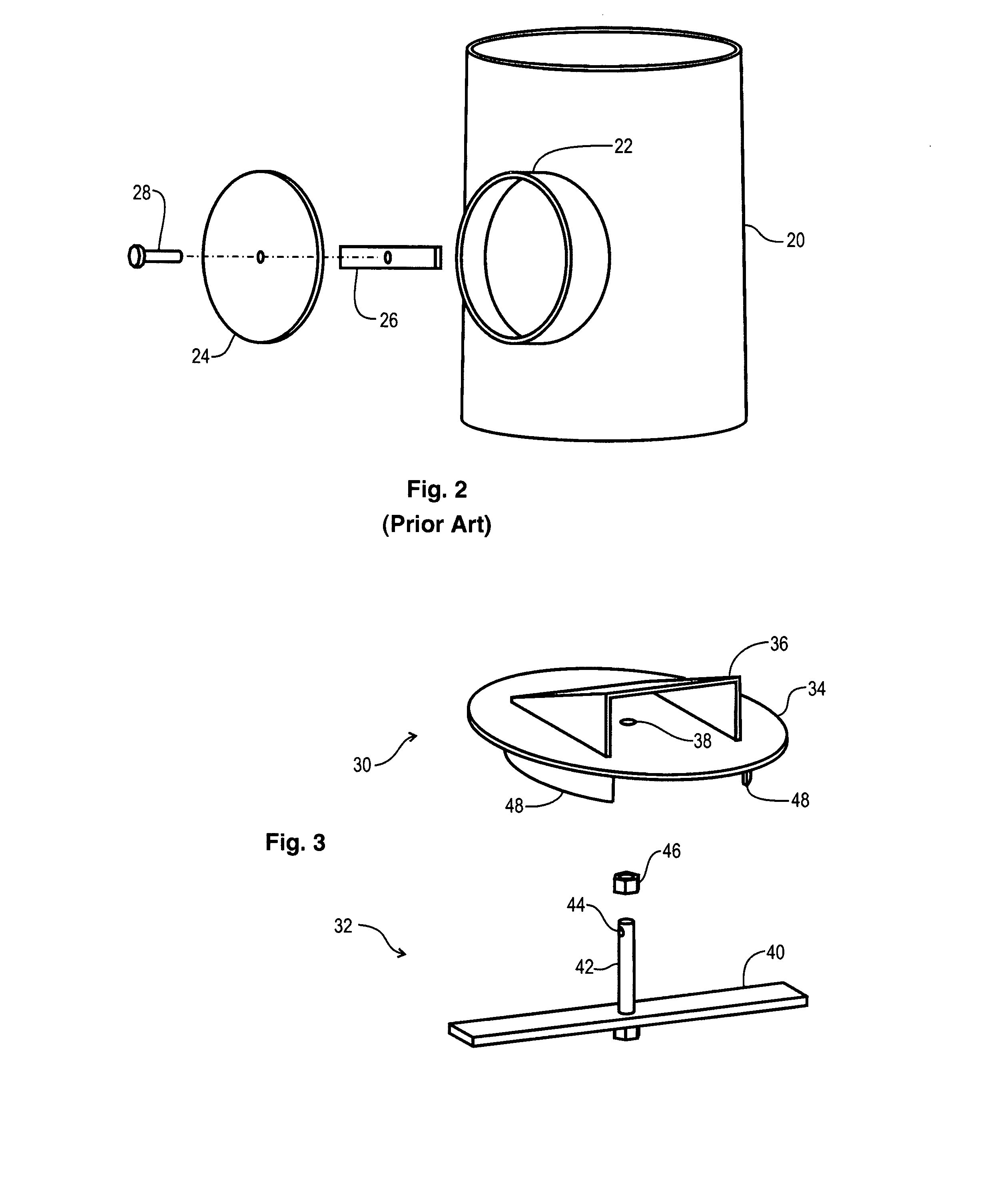
[0007]In a specific embodiment of the security cover, where the enclosure is an electrical enclosure, the security cover is adapted to prevent the theft of copper wiring disposed within the enclosure. In another specific embodiment, the access opening is a hand-hole having a frame fixed to the enclosure, and the clamp-bar engages the hand-hole frame in the interior of the enclosure. In another specific embodiment, the shroud has three sides and an exterior front surface, and the access port is formed through omission of a fourth side of the shroud. In another embodiment, the cover, the alignment flange, and the shroud are welded to form an integral unit. In another specific embodiment, the clamp-bar and the lock-bar are welded to form an integral unit. In another specific embodiment, wherein the lock-bar is threaded along its second end, a retaining nut is threadably engaged to the second end between the exterior surface of the rigid cover and the shackle hole.
[0011]In a specific embodiment of the foregoing securing cover, where the enclosure is a ground-installed electrical enclosure, the security cover is adapted to prevent the theft of copper wiring disposed within the enclosure. In another specific embodiment, the frame further includes at least a first opening formed therein, and the cover further includes at least a first cover tang that extends from its exterior side, which engages the first opening in the frame, and thereby retains the cover to the frame. In another specific embodiment, the lock shroud includes three sides and an exterior front surface, and the access port is formed by omitting a fourth side of the shroud. In another specific embodiment, the securing cover further includes plural hinges disposed between the frame and the plural engaging members to provide the flexibly coupling of the engaging members to the frame. In another specific embodiment, the plural urging means are threaded fasteners disposed to rotate the plural engaging means outwardly, which thereby engage the interior of the enclosure and retains the frame in position. In another specific embodiment, wherein the enclosure includes its own exterior cover, the rigid cover further includes at least a first fastening means disposed thereon for access from the exterior surface thereof, for engaging at least a first fastener for retaining the exterior cover about the exterior surface of the rigid cover.
[0012]The present invention teaches a method of selectively securing, against theft, the electrical wiring in a utility pole that has a hand-hole designed for use with a conventional hand-hole cover. The method includes the steps of inserting a clamp-bar and lock-bar unit into the hand-hole and aligning the clamp-bar portion to engage an interior surface of the utility pole such that an end of the lock-bar having a shackle hole formed therein is exposed on the exterior of the hand-hole, and, substantially covering the hand-hole with a rigid cover, and aligning at least a first flange extending from the interior surface of the rigid cover with the hand-hole. And, the steps of engaging a lock-bar opening formed in the rigid cover about the lock-bar such that the shackle-hole of the lock-bar is presented within a shroud, that has an excess port, on the exterior surface of the rigid cover, and, inserting a padlock into the access port of the shroud and engaging the padlock shackle with the shackle hole in the lock-bar, and also, locking the padlock, thereby securing access to the electrical wiring against theft.
[0013]The present invention teaches a method of selectively securing, against theft, the electrical wiring in an electrical enclosure that has an access opening designed for use with a conventional cover. The method includes the steps of aligning a frame to the access opening in the electrical enclosure, where the frame has a lock-bar with a shackle hole extending from its exterior side and plural engaging members flexibly coupled thereto and extending beyond its interior side, and, operating plural urging means correspondingly disposed between the frame and the plural engaging members, thereby urging the plural engaging members against interior surfaces of the enclosure, and thereby fixedly retaining the frame to the access opening of the electrical enclosure. The method also includes attaching a rigid cover, that has a lock-bar opening formed therein, to substantially cover the frame, such that the shackle-hole of the lock-bar passes through the lock-bar opening and is presented within a shroud, having an access port, on the exterior surface of the rigid cover. The method further includes inserting a padlock into the access port of the shroud and engaging the padlock shackle with the shackle hole in the lock-bar, and locking the padlock, thereby securing access to the electrical wiring against theft.

Problems solved by technology

A serious problem has arisen in recent years.
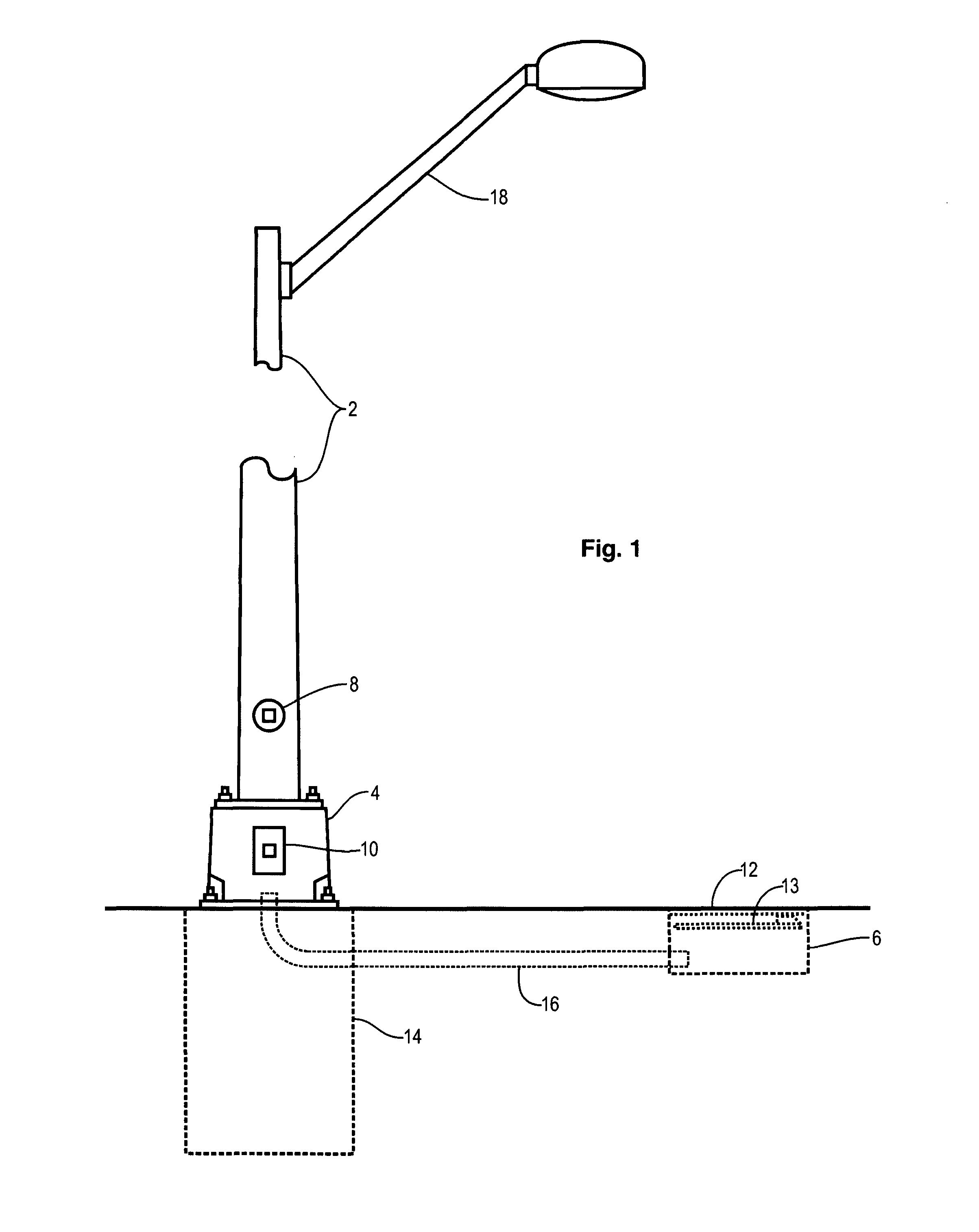
Due to increasing value of scrape metals, copper in particular, and the unrestrained desire by certain segments of society to acquire cash from the sales of scrap metals, there has been a explosion in the frequency of theft of copper wiring from utility poles and related junction boxes and conduits.
Of course, such action is ungraceful and frequently causes damage to the wiring, fixtures, and even the poles and junction boxes themselves.
In fact, there have been occurrences where wiring has been stolen several times from the same utility pole installation.

Method used


Image

  • Security cover for a utility pole and enclosure and method
  • Security cover for a utility pole and enclosure and method
  • Security cover for a utility pole and enclosure and method

Examples


Embodiment Construction

[0030]Illustrative embodiments and exemplary applications will now be described with reference to the accompanying drawings to disclose the advantageous teachings of the present invention.

[0031]While the present invention is described herein with reference to illustrative embodiments for particular applications, it should be understood that the invention is not limited thereto. Those having ordinary skill in the art and access to the teachings provided herein will recognize additional modifications, applications, and embodiments within the scope hereof and additional fields in which the present invention would be of significant utility.

[0032]In considering the detailed embodiments of the present invention, it will be observed that the present invention resides primarily in combinations of steps to accomplish various methods and components to form various apparatus. Accordingly, the apparatus components and method steps have been represented where appropriate by conventional symbols ...


PUM


Abstract

A security cover for selectively securing an access opening in an enclosure or a utility pole using a padlock with a shackle. The security cover includes a rigid cover, that substantially covers the access opening and has a lock-bar opening formed therethrough. A shroud is fixed about the lock-bar opening on the exterior surface of the rigid cover, and the shroud has an access port for enabling insertion of the padlock between the shroud and the exterior surface of the rigid cover. A lock-bar extends through the lock-bar opening in the rigid cover while the clamp-bar is engaged with the interior of the enclosure. The shackle-hole is accessible through the access port of the shroud.

Description

BACKGROUND OF THE INVENTION[0001]1. Field of the Invention[0002]The present invention relates to security covers for enclosures. More specifically, the present invention relates to security covers used to protect the electrical wiring in utility poles and electrical junction boxes.[0003]2. Description of the Related Art[0004]Utility poles are in use throughout the world for area lighting, street lighting, sports complex lighting, security cameras, traffic control and monitoring applications, overhead wiring support, wind turbines, radio antenna support, weather instruments, and many other applications. Utility poles are frequently used as a conduit for electrical wiring and cables from ground level to overhead fixtures or various sorts. Electrical junction boxes and electrical conduits are commonly used in combination with utility poles, to facilitate the routing and distribution of electrical power and signaling circuits. Since such wiring and cables must be installed and maintaine...

Claims


Application Information

Patent Timeline
IPC IPC(8): H02G7/20
CPCE04H12/003H02G3/14H02G2200/10F21S8/08
Inventor OUSLEY, RICHARD L.
Owner LIGHTING SECURITY PRODS
Learn More