
Cup attaching apparatus

a technology for attaching apparatuses and cups, which is applied in the field of attaching apparatuses for cups, can solve the problems of complex apparatus configuration, large sized apparatus, and inability to accurately attach cups, etc., and achieve the effect of accurate attaching the cup

Active Publication Date: 2011-02-08
NIDEK CO LTD
View PDF7 Cites 12 Cited by
  • Summary
  • Abstract
  • Description
  • Claims
  • Application Information

AI Technical Summary

Benefits of technology

The apparatus achieves accurate cup attachment without a complicated configuration, effectively detecting optical centers and cylinder axis angles, and clearly imaging lens edges and marks, enhancing detection accuracy and simplifying the apparatus design.

Problems solved by technology

Such an apparatus using the screen would have problems in detection accuracy because the measurement index image is blurred due to roughness of the screen, and the mark point image, the small lens portion image of the bifocal lens, the mark image of the progressive focal lens, and others are projected in blurred and distorted states onto the screen due to refractive powers of the lenses.
Moreover, the apparatus arranged to illuminate the lens by the diffused illumination light from the back surface side of the lens could not easily detect (determine) an outer edge of the lens, a small lens portion edge of the bifocal lens, and others.
In the apparatus disclosed in EP 1739472A1 (JP2005-316436A), the optical system for detecting an optical center of the lens and others forms an optical path different from that of the optical system for imaging the lens image, resulting in a complicated apparatus configuration and a large sized apparatus.

Method used


Image

  • Cup attaching apparatus
  • Cup attaching apparatus
  • Cup attaching apparatus

Examples


Embodiment Construction

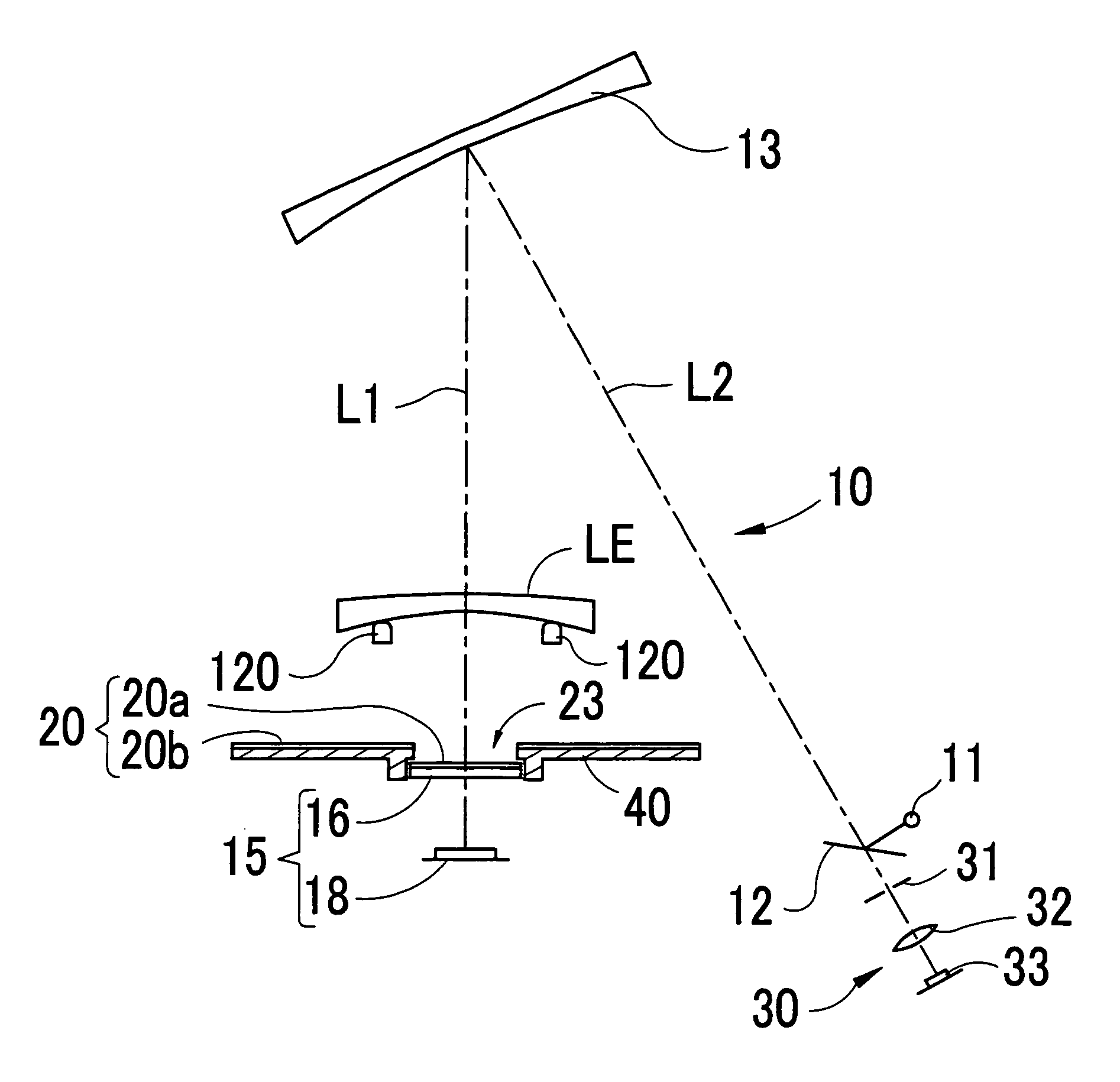
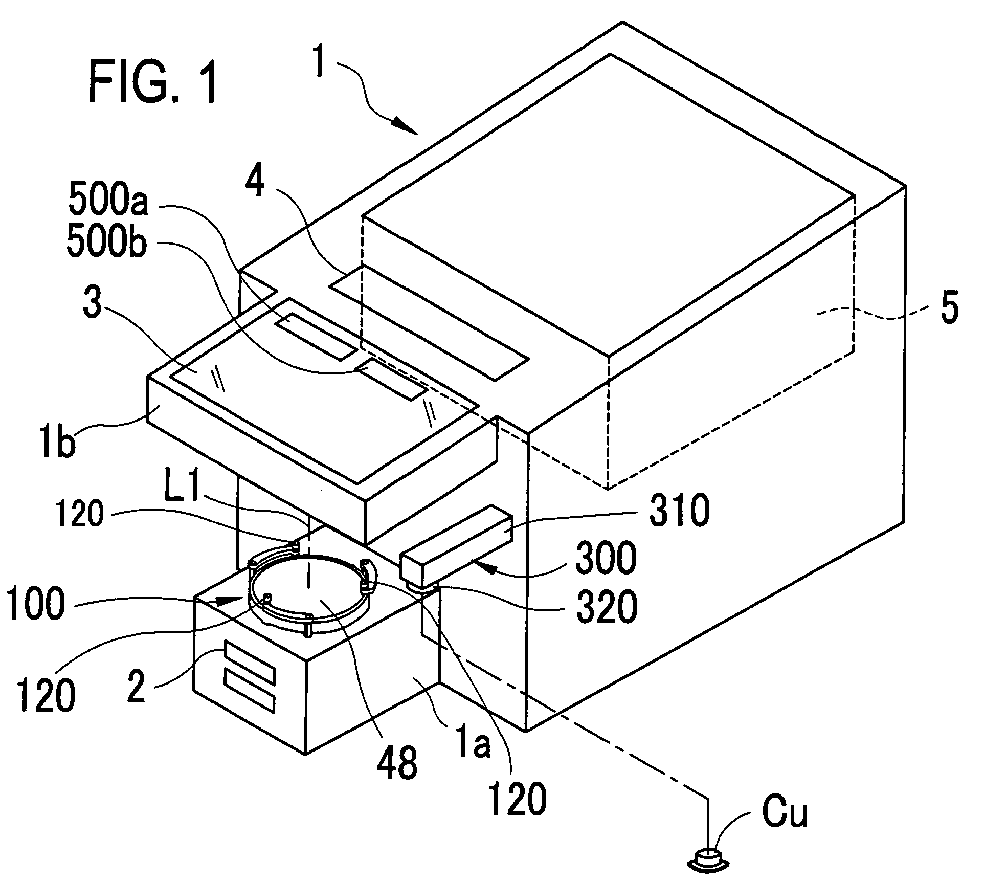
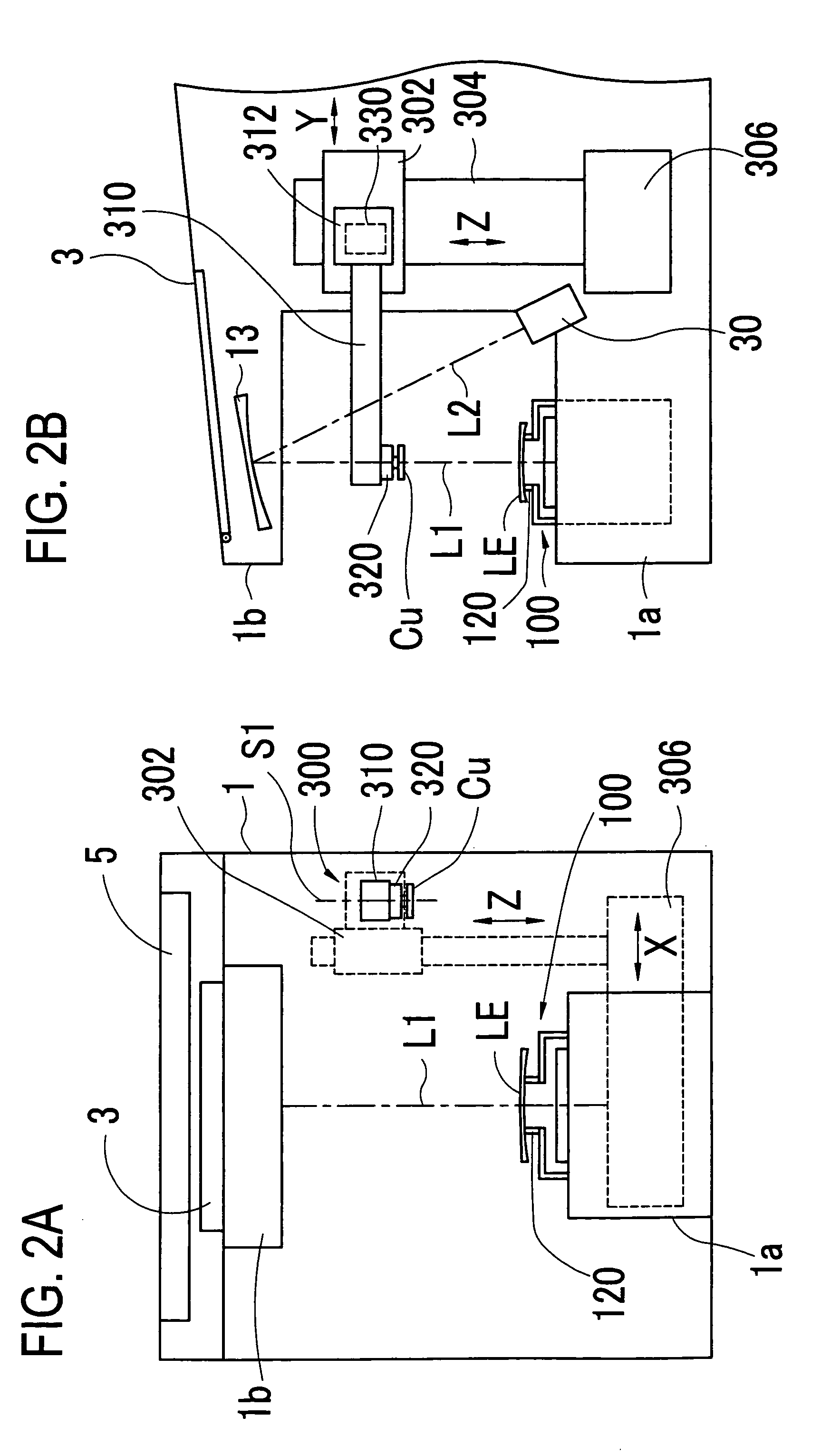
[0030]A detailed description of a preferred embodiment of the present invention will now be given referring to the accompanying drawings. FIG. 1 is a schematic perspective view of a cup attaching apparatus of this embodiment of the invention. FIGS. 2A and 2B are schematic configuration views of a partial inner structure of the apparatus; FIG. 2A is a front view of the apparatus and FIG. 2B is a side view thereof.

[0031]An apparatus main unit 1 has a laterally-facing U-shaped box form in a side view. In an upper portion of the main unit 1, an eyeglass frame measurement unit 5 is installed. In front thereof, an operation switch part 4 for the measurement unit 5 and a color display touch panel 3 are arranged. On a base part 1a extending forward from the main unit 1, a lens support mechanism 100 is placed, having three support pins 120 on which a lens LE is to be mounted. On a right portion of the main unit 1, a cup attaching mechanism 300 for attaching (fixing) a cup Cu to a front surfa...


PUM


Abstract

A cup attaching apparatus for attaching a cup as a processing jig to an eyeglass lens including an illumination optical system including an illumination light source arranged to illuminate a side of the front surface of the lens by light from the light source; an imaging optical system including an imaging device and a retroreflection member placed on an opposite side from the light source with respect to the lens; an image processing device adapted to process an image signal from the imaging device to detect at least one of a mark point provided on a unifocal lens, a small lens portion of a bifocal lens, and a progressive mark provided on a progressive focal lens and obtain a position of the detected one; and an arithmetic control device adapted to determine an attaching position of the cup based on the position obtained by the image processing device.

Description

BACKGROUND OF THE INVENTION[0001]1. Field of the Invention[0002]The present invention relates to a cup attaching apparatus for attaching a cup as a processing jig used for processing an eyeglass lens to a surface of the lens.[0003]2. Description of Related Art[0004]As a cup attaching apparatus, there is known an apparatus comprising an illumination optical system for projecting illumination light to a lens from a front surface side of the lens, a measurement index of a predetermined pattern and a screen placed at a back surface side of the lens, and an imaging optical system including an imaging device for imaging an image of the measurement index and an image of the lens projected on the screen. This apparatus is arranged to detect an optical center and a cylinder axis angle of the lens by processing an image signal from the imaging device, and determine an attaching position of the cup based on a detection result thereof (e.g., see U.S. Pat. No. 6,798,501B1 (JP2000-79545A)). Such ...

Claims


Application Information

Patent Timeline
Patent Type & Authority Patents(United States)
IPC IPC(8): G01B9/00
CPCB24B13/0012B24B13/0055
Inventor MIZUNO, TOSHIAKIMATSUYAMA, YOSHINORIMATSUMOTO, TOSHIROSUZUKI, KENJIIMAIZUMI, SATOSHI
Owner NIDEK CO LTD
Learn More