Rotor position sensing apparatus and method using piezoelectric sensor and hall-effect sensor

a piezoelectric sensor and rotor technology, applied in the direction of motor/generator/converter stopper, dynamo-electric converter control, instruments, etc., can solve the problems of reducing the guaranteed maximum starting torque, low starting torque and in the initial reverse rotation of the rotor, source of noise and vibration, etc., to achieve the near-maximum start-up torque, improve the effect of start-up performance and reduce the number of hall sensors

Inactive Publication Date: 2011-02-08
PURDUE RES FOUND INC
View PDF3 Cites 48 Cited by
  • Summary
  • Abstract
  • Description
  • Claims
  • Application Information

AI Technical Summary

Benefits of technology

[0012]Several advantages of the observer are 1) near-maximum start-up torque is guaranteed 2) no reverse rotation of the rotor occurs during startup, 3) sufficient precision of rotor position is estimated to achieve torque harmonic control, 4) the observer does not require knowledge of back-emf or cogging torque harmonics, 5) is applicable to machines with arbitrary back-emf waveform and stator slot configuration, and 6) is relatively low-cost.
[0013]One embodiment of the CPSH has been validated in hardware using a 3-phase, 8-

Problems solved by technology

Although, the methods in [1-8] have shown reasonable success, they have limitations.
In [5-6], the use of a single Hall-effect sensor further reduces the guaranteed maximum starting torque.
Specifically, in [6], the synchronous excitation used during start-up can result in low starting torque and in an initial reverse rotation of the rotor.
In PMSM drives, a dominant source of noise

Method used


Image

  • Rotor position sensing apparatus and method using piezoelectric sensor and hall-effect sensor
  • Rotor position sensing apparatus and method using piezoelectric sensor and hall-effect sensor
  • Rotor position sensing apparatus and method using piezoelectric sensor and hall-effect sensor

Examples


Embodiment Construction

[0029]For the purpose of promoting an understanding of the principles of the invention, reference will now be made to the embodiments illustrated in the drawings and specific language will be used to describe the same. It will nevertheless be understood that no limitation of the scope of the invention is thereby intended, such alterations and further modifications in the illustrated device and such further applications of the principles of the invention as illustrated therein being contemplated as would normally occur to one skilled in the art to which the invention relates.

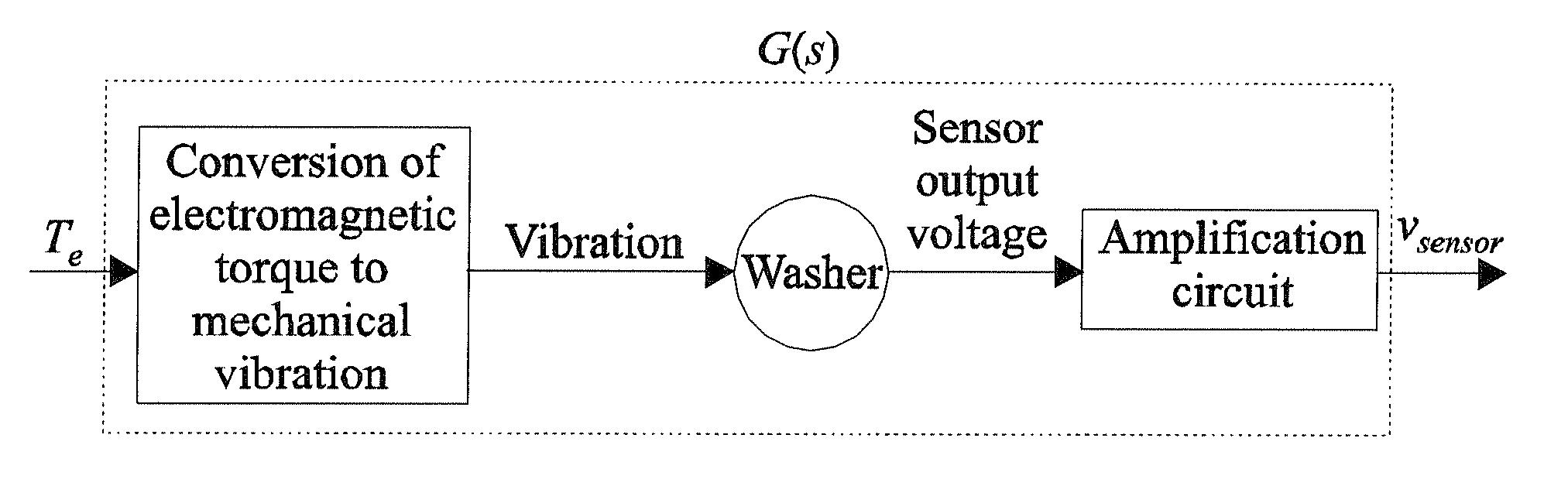
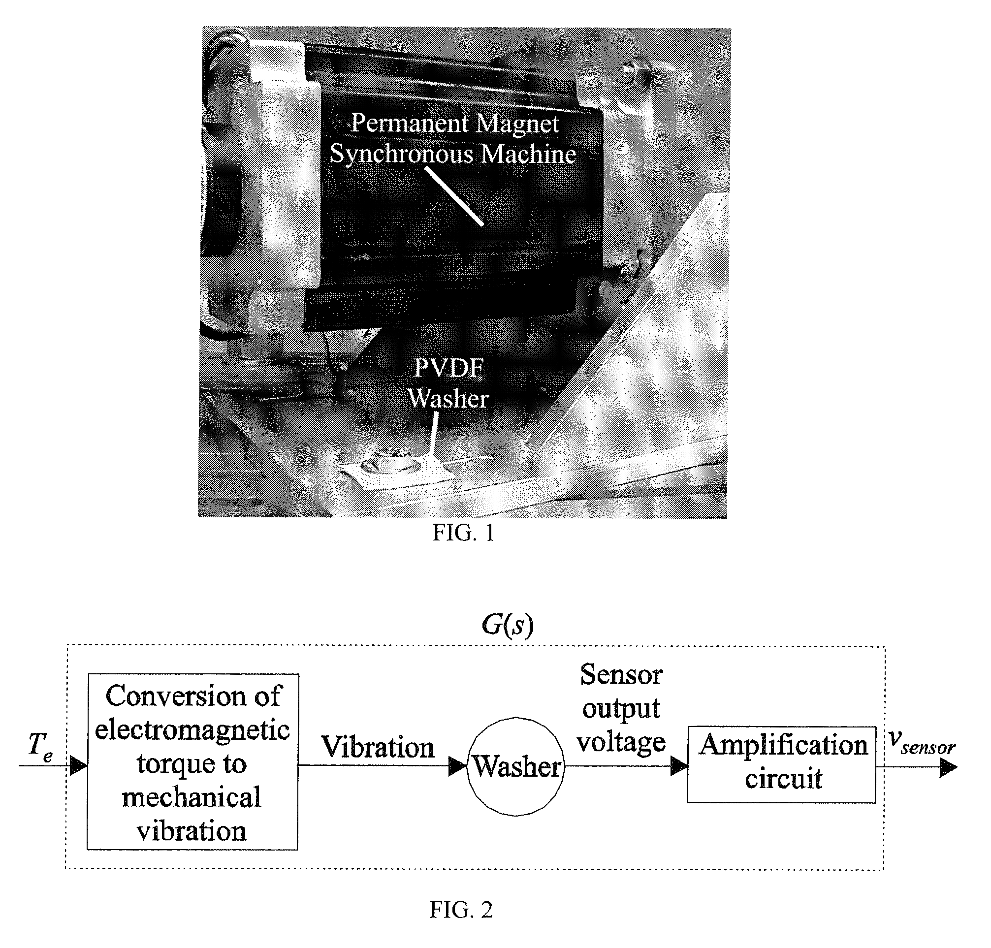
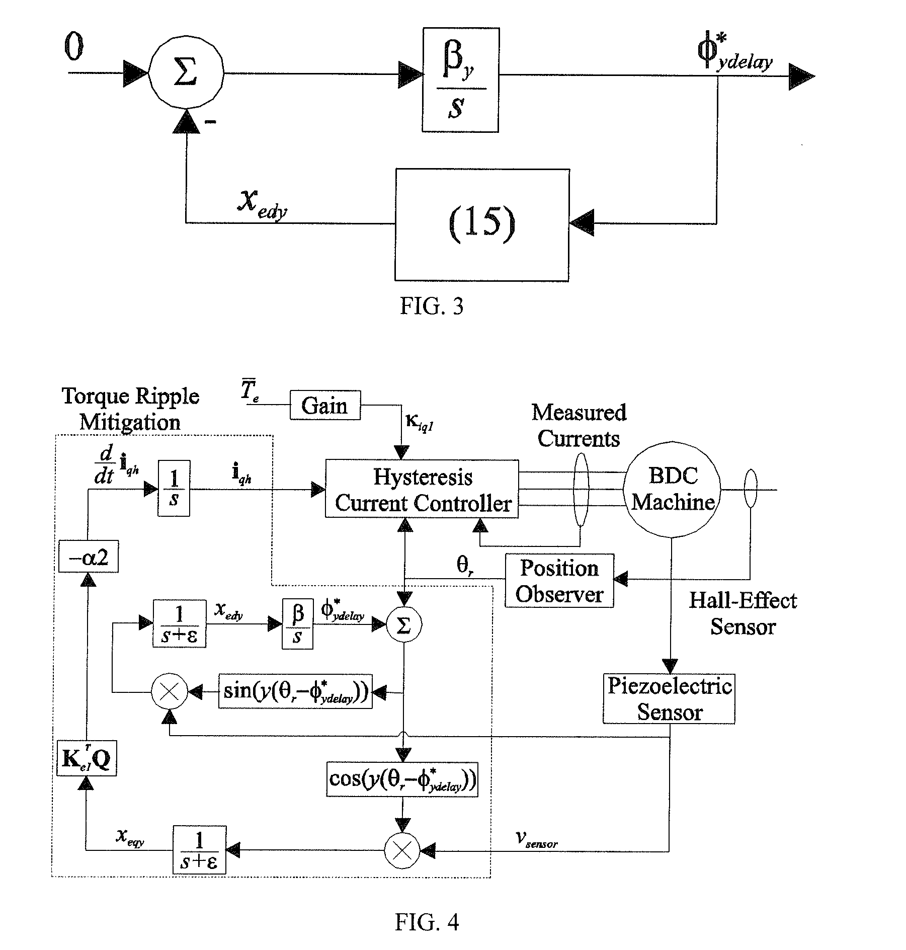
I. Measurement and Mitigation of Torque Ripple Induced Vibration

[0030]The position observer disclosed herein utilizes a piezoelectric polymer, whose primary function is to provide torque ripple feedback. A picture of the sensor implementation is shown in FIG. 1. Therein, it can be seen that the sensor is a washer that is placed on a bolt on the machine's mount bracket. Details of the sensor properties are describ...


PUM


Abstract

A position observer for control-based torque ripple mitigation in permanent magnet synchronous machines (PMSMs). Rotor position is determined using data from two sources: a piezoelectric sensor for initial position and low-speed detection, and a single Hall-effect sensor for high-speed detection.

Description

CROSS REFERENCE TO RELATED APPLICATIONS[0001]This application claims the benefit of U.S. Provisional Patent Application No. 60 / 868,983, filed Dec. 7, 2006, and application No. 60 / 869,138, filed Dec. 8, 2006.GOVERNMENT RIGHTS[0002]This invention was made with government support under N00024-02-C-4056 with the Naval Sea Systems Command. The government has certain rights in the invention.BACKGROUND OF THE INVENTION[0003]This invention relates to electric motor controls, and more particularly to devices and methods for determining the position of a rotor of an electric motor.[0004]In drive-based control of permanent magnet synchronous machines (PMSM), knowledge of rotor position is required to control electromagnetic torque. In practice, numerous methods of measuring or estimating position are applied. Traditionally, for machines that have a trapezoidal back-emf, 120° square wave excitation is utilized. Under 120° excitation, three Hall-effect sensors placed at 120° intervals provide su...

Claims


Application Information

Patent Timeline
IPC IPC(8): G01L3/10
CPCH02K11/001H02P6/10H02P6/16H02P6/20H02K29/03H02P2209/07H02K11/20
Inventor PEKAREK, STEVEN D.BECCUE, PHILIP B.
Owner PURDUE RES FOUND INC
Why Eureka
Try Eureka