Method for activating a weapon with an identification mechanism

Inactive Publication Date: 2011-02-15
VALUE PRIVATSTIFTUNG
View PDF42 Cites 18 Cited by
  • Summary
  • Abstract
  • Description
  • Claims
  • Application Information

AI Technical Summary

Benefits of technology

[0007]The purpose of the present invention is to prevent the use of a weapon by unauthorized

Problems solved by technology

Since input of the identification code takes a certain amount of time, such a weapon is not suited for use in a dangerous situation.
However, in these systems, communication between the transmitter and r

Method used


Image

  • Method for activating a weapon with an identification mechanism
  • Method for activating a weapon with an identification mechanism

Examples


Embodiment Construction

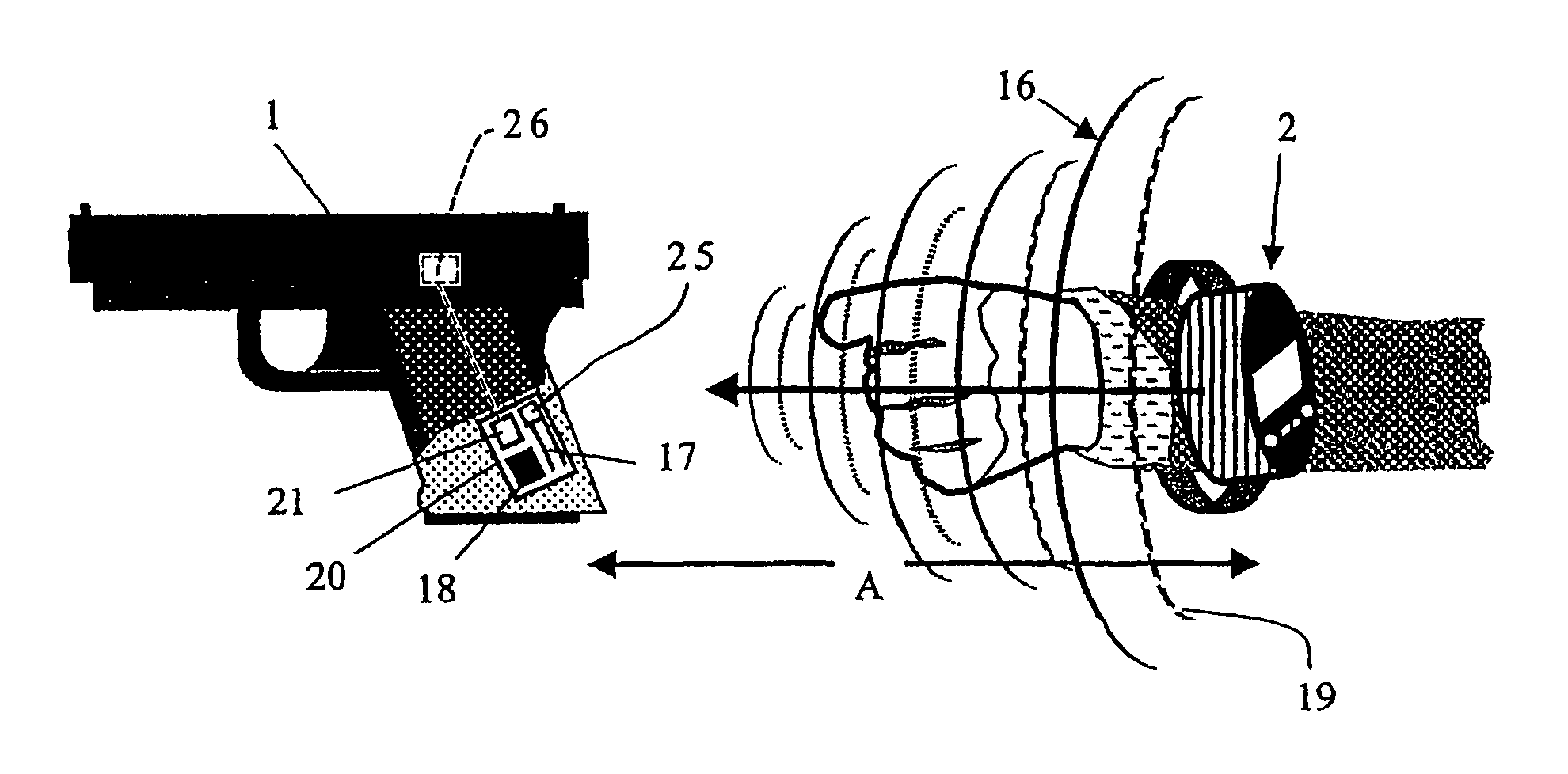
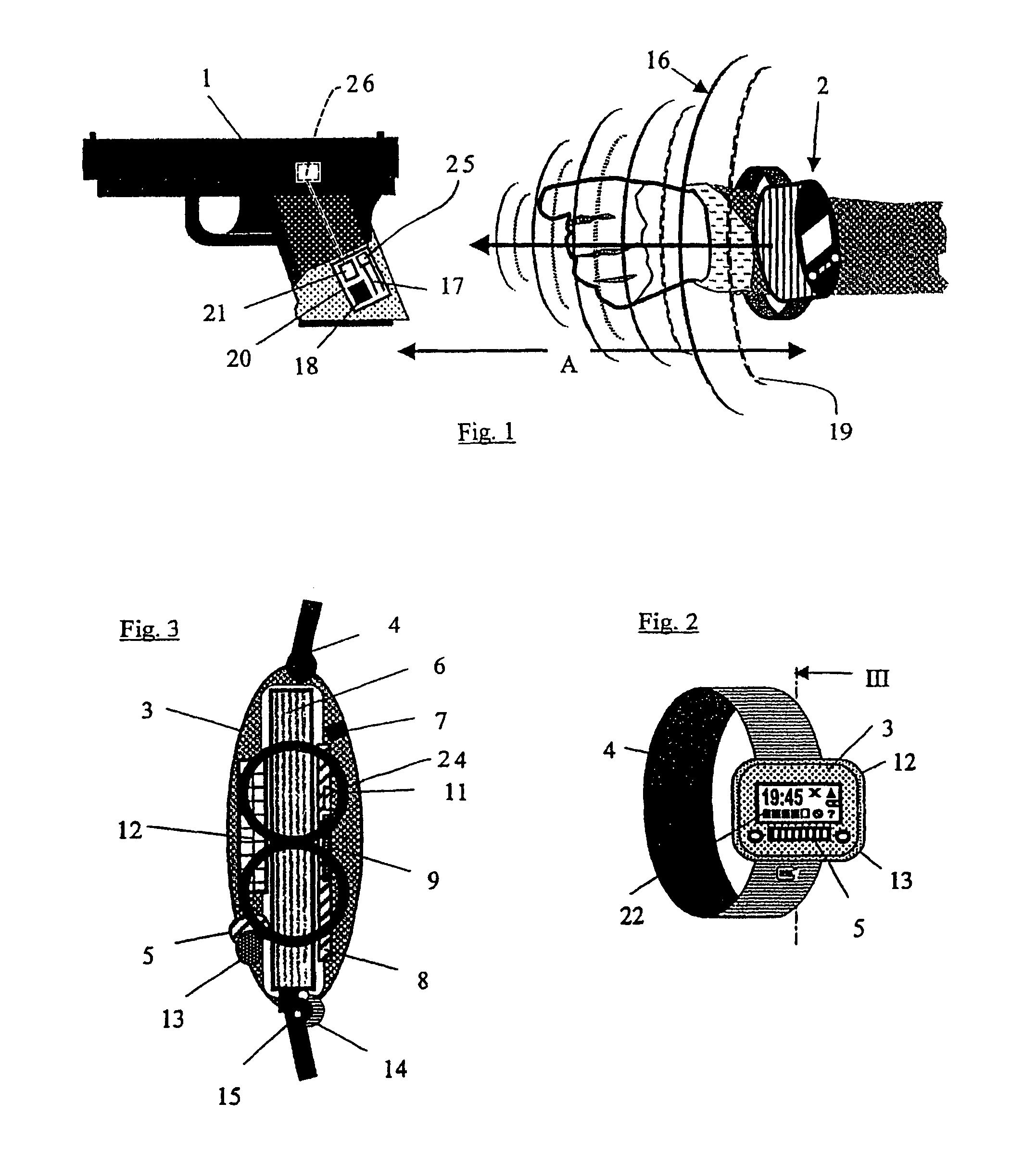
[0026]Referring to FIG. 1 the user carries a weapon 1, such as a pistol 1, and an identification mechanism 2. When the identification mechanism 2 is carried on a wristwatch as illustrated in FIGS. 2 and 3, the identification mechanism 2 is worn on the user's wrist. Such an identification mechanism 2 has a housing 3 and a wristband 4.

[0027]As illustrated in FIGS. 2 and 3, the identification mechanism 2 includes a sensor for detecting an identification code, namely a fingerprint reader 5, which is preferably a CCD sensor. The housing 3 also houses an accumulator 6, which is charged through a charging contact 7 or in another suitable manner, such as inductively. The fingerprint reader 5, an RF transmitter including the antenna 11, an LCD indicator 12 and the other electronic components of the identification mechanism 2 are controlled by a microprocessor 9 which is included on a printed circuit 8. A function key 13 is provided on the identification mechanism 2 and is configured to indic...


PUM


Abstract

A system for activating a weapon to a state of readiness to fire includes an identification mechanism which is carried by the user of the weapon. The identification mechanism includes a sensor configured to input an identification code, a store configured to store the identification code and a transmitter. A receiver is provided in the weapon. The transmitter sends an activation signal to the receiver upon a positive identification code comparison. The activation signal activates the weapon to a state of readiness to fire. To maintain the weapon in this activation state, the transmitter continuously emits a signal to the receiver. The receiver controls a processor which is configured to maintain the weapon in the activation state based exclusively on the strength of the signals continuously being received by the receiver. To maintain the weapon in this state, the strength of the received signals must be equal to or greater than the strength of the signals received by the receiver when the identification mechanism is at a specified distance from the weapon.

Description

[0001]This application is a divisional of U.S. patent application Ser. No. 10 / 263,373 filed Oct. 2, 2002, now abandoned.FIELD OF THE INVENTION[0002]The present invention relates to a system for activating a weapon to a state of readiness to fire.BACKGROUND OF THE INVENTION[0003]In order to prevent the use of a weapon by unauthorized persons, it is known to provide a sensor on the handle of the weapon to receive an identification code. One example of such a sensor is a fingerprint reader. Since input of the identification code takes a certain amount of time, such a weapon is not suited for use in a dangerous situation.[0004]Alternative systems are known, wherein the user of the weapon carries an identification mechanism, such as a wristband, a wristwatch, a ring, gloves or the like, which is compatible with the sensor to read-in the identification code. The identification code can be, for example, a PIN code or a fingerprint pattern. The authorized user of the weapon, for example a p...

Claims


Application Information

Patent Timeline
IPC IPC(8): F41A17/00F41A17/06
CPCF41A17/063F41A17/066
Inventor GLOCK, GASTON
Owner VALUE PRIVATSTIFTUNG
Why Eureka
Try Eureka