Plant pot

a plant pot and container technology, applied in the field of plant pots, can solve the problems of reducing yield, consuming time, labor-intensive and time-consuming so as to achieve the effect of simple assembly and robust rim structur

Inactive Publication Date: 2011-02-15
CHEN ROBERT
View PDF7 Cites 23 Cited by
  • Summary
  • Abstract
  • Description
  • Claims
  • Application Information

AI Technical Summary

Benefits of technology

[0008]The main objective of the present invention is to provide a plant pot with a robust rim structure and simple assembly.
[0010]Based on a structure of the plant pot as described above, the fixing posts and corresponding fixing barrels enhance strength of the collar of the container in combination with the ring cover. Thus, height between the collar and the ring cover can be increased so increasing durability of the plant pot. Moreover, the ring cover is held firmly on the collar by engagement of the fixing posts and fixing barrels, which prevents the ring cover from being rotated and detached from the container. Furthermore, the fixing posts protrude out from the collar away from the bottom of the container, which corresponds to flow direction of filling material during injection molding so a defect rate of manufacture is also minimized. Therefore, yields of plant pots in accordance with the present invention are increased.

Problems solved by technology

However, the decorative rim structure and the body of the plant pot have different contraction rates during manufacture by injection molding resulting in consuming time and decreasing the yield.
Further, in both convention plant pot structures described, forming multiple projections on the decorative rim structure or the collar (31) of the decorative rim structure (30) to increase diversity is labor-intensive and time-consuming so is relatively expensive.
Although the panels (51) strengthen the decorative structure (40), this design complicates manufacturing procedures of the conventional plant pot with the decorative rim structure (40) and also increases a rate of defects.

Method used


Image

  • Plant pot
  • Plant pot
  • Plant pot

Examples


Embodiment Construction

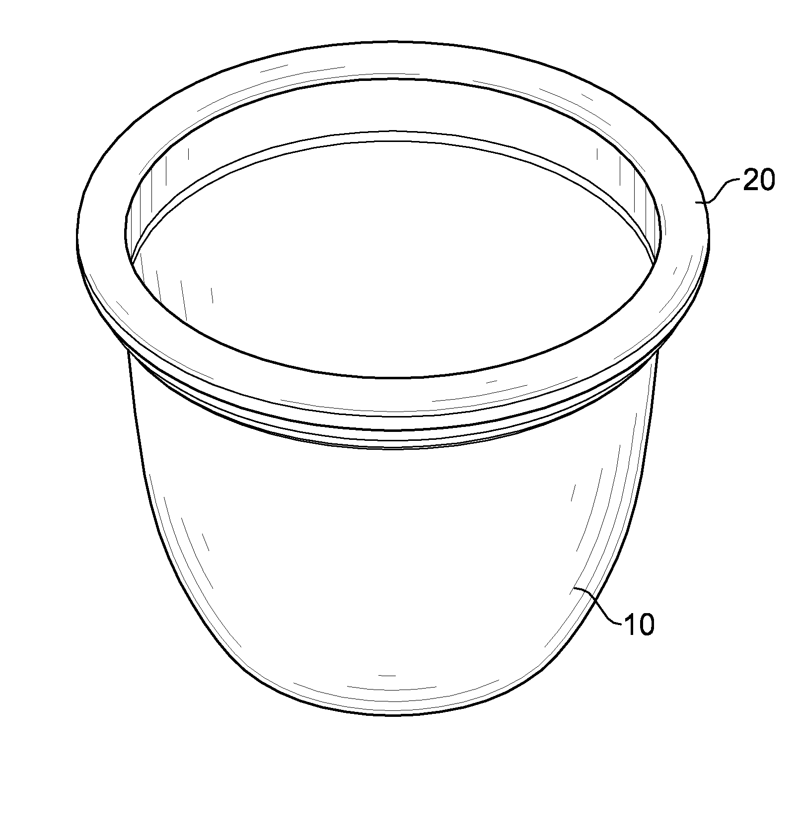
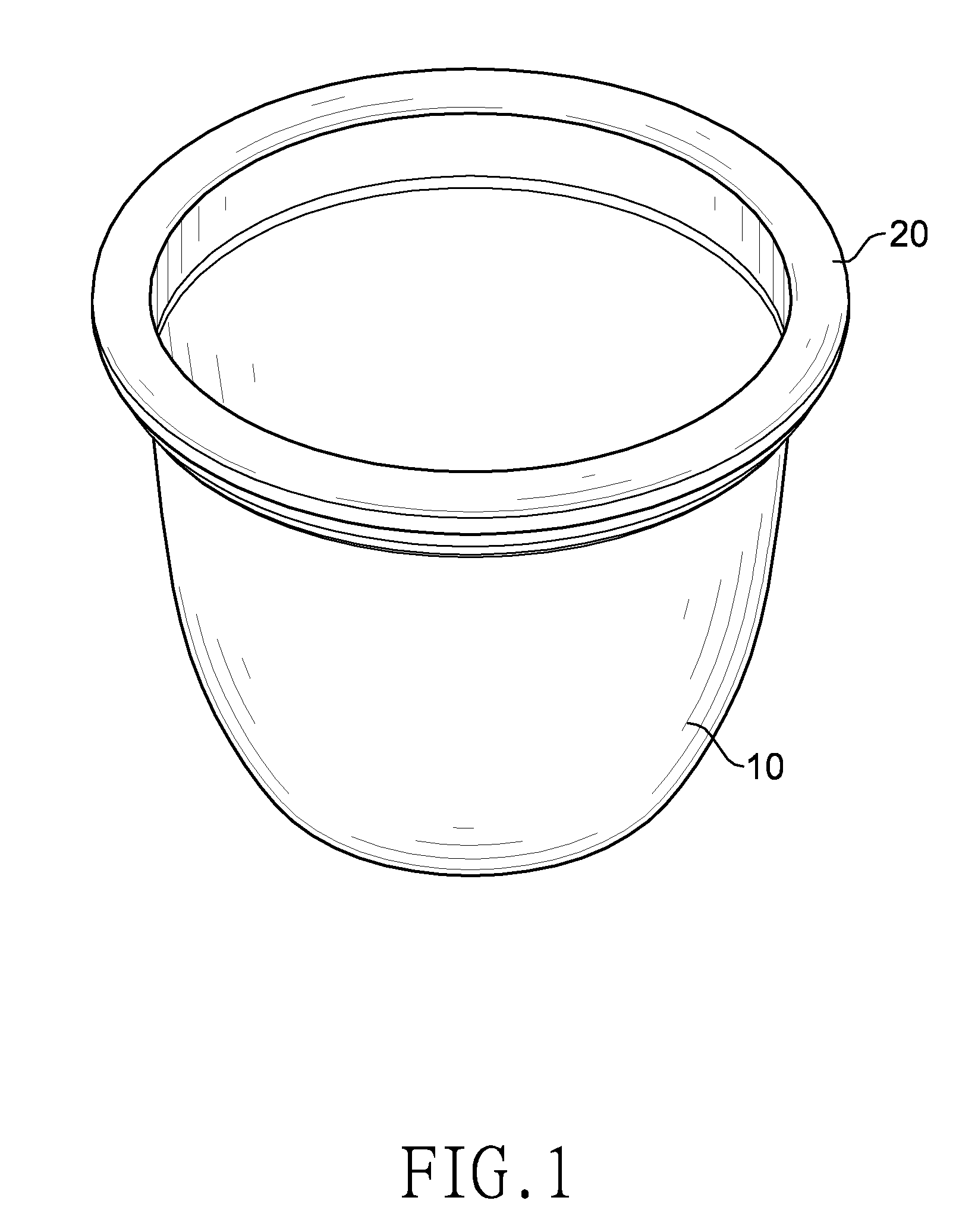
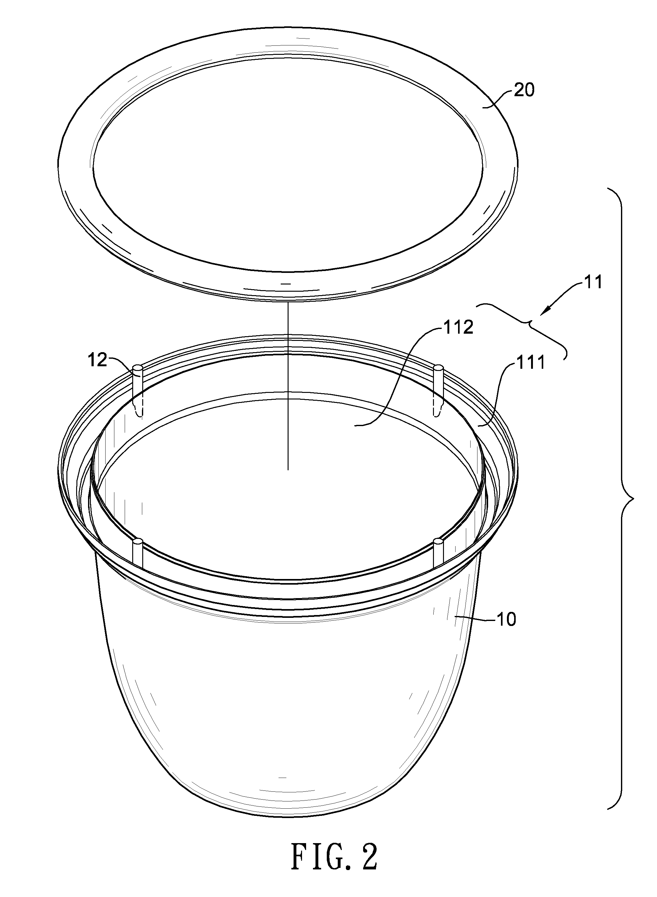
[0020]A plant pot in accordance with the present invention, as shown in FIG. 1, comprises a container (10) and a ring cover (20).

[0021]The container (10), with further reference to FIGS. 2 and 3, is a hollow cylinder and has a top, a bottom, a sidewall (11), multiple fixing posts (12), an optional outer protrusion (13) and an optional inner protrusion (14). The sidewall (11) defines a chamber and has a collar (111) and a base section (112). As shown in FIG. 4, the collar (111) is annular, is attached to an upper edge of the base section (112) and has a periphery, an interior edge and multiple optional concave segments. The concave segments are annular and formed stepwise between the periphery and the interior edge of the collar (111). The fixing posts (12) are formed on and protrude out from the collar (111) away the bottom the container (10). The outer protrusion (13) is formed on the periphery of the collar (111). The inner protrusion (14) is formed on the interior edge of the col...


PUM


Abstract

A plant pot has a container and a ring cover. The container has a top, a sidewall and multiple fixing posts. The sidewall has an annular collar. Each fixing post protrudes out from the collar. The ring cover is mounted over the collar of the sidewall of the container and has an inner edge, an outer edge and multiple fixing barrels. The inner edge and the outer edge are attached to the sidewall of the container. Each fixing barrel is formed on and protrudes out from the inner surface of the ring cover and has a corresponding fixing post. Engagement of the fixing posts to the fixing barrels prevents the ring cover from being rotated relative to and detached from the container.

Description

BACKGROUND OF THE INVENTION[0001]1. Field of the Invention[0002]The present invention relates to a container for growing plants, particularly to a plant pot having an enhanced decorative rim structure.[0003]2. Description of the Prior Arts[0004]Plant pots are containers for culturing plants. For decorative purposes, a decorative rim structure mounted on a top edge of a body of the plant pot has been designed. To increase strength of the decorative rim structure to support a weight of the plant pot during transposition, the decorative rim structure is designed to be solid, not hollow. However, the decorative rim structure and the body of the plant pot have different contraction rates during manufacture by injection molding resulting in consuming time and decreasing the yield. Due to limitations of injection molding and differing contraction times, another conventional plant pot with decorative rim structure is designed.[0005]The conventional plant pot, as shown in FIGS. 5 and 6, has ...

Claims


Application Information

Patent Timeline
Patent Type & Authority Patents(United States)
IPC IPC(8): A01G9/02B65D8/08
CPCA01G9/02
Inventor CHEN, ROBERT
Owner CHEN ROBERT
Why Eureka
Try Eureka