
Hydraulic unit

Active Publication Date: 2011-02-22
HYDAC TECH GMBH
View PDF6 Cites 10 Cited by
  • Summary
  • Abstract
  • Description
  • Claims
  • Application Information

AI Technical Summary

Benefits of technology

An object of the present invention is to provide an improved, energy-efficient hydraulic unit at low cost.
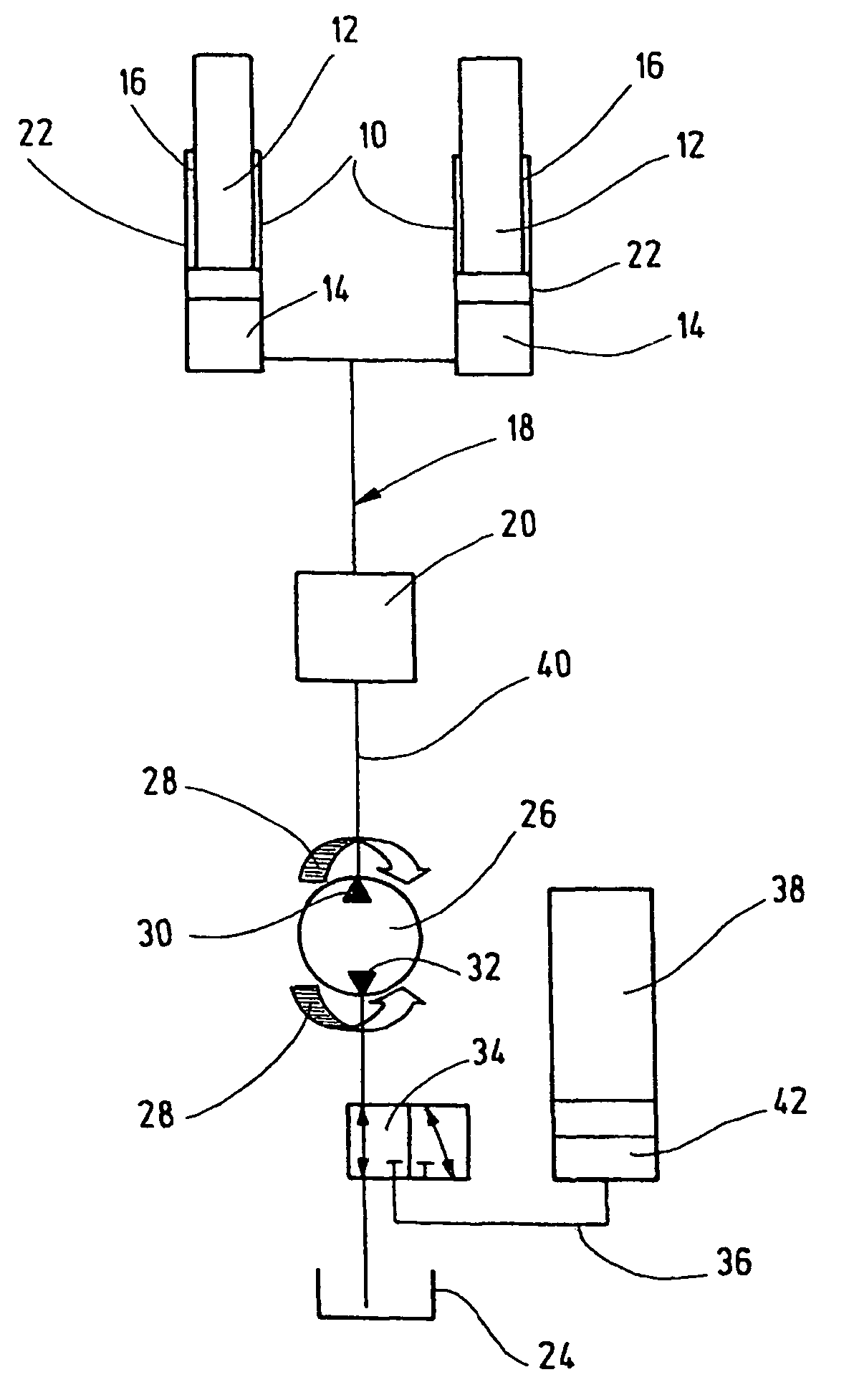
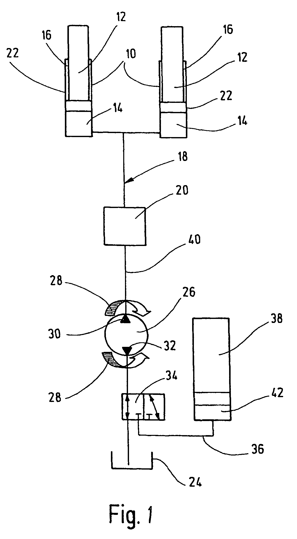
This object is basically achieved by a hydraulic unit including a storage device which feeds energy in one direction of driving of the hydraulic pump. The supplied energy can be retrieved from the storage device to support displacement movement for the opposite driving direction of the hydraulic pump. In particular, the movement of load lifting can be carried out with energy support from the storage device. This arrangement results in lower driving power for the hydraulic pump with its motor. The retrieved energy at a high pressure level of the fluid from the storage device can also be used for faster displacement movements on the respective working cylinder. This use benefits a high-speed operating process. By using the storage device, overall harmonical operation of the entire hydraulic unit without jolts can be achieved. By simply reversing the direction of rotation of the hydraulic pump, the amount of fluid displaced from the working cylinder when the load is lowered can be pushed into the storage device to increase the pressure level and can be retrieved again from there in the next working cycle.
In spite of the expected additional costs for an additional storage device, preferably in the form of a hydraulic accumulator, the expected savings due to energy-efficient operation can be assumed to be higher. Even for a short interval of use of energy storage, these additional costs are equalized. Operating costs overall can therefore be reduced in these hydraulic units by using the storage device.

Problems solved by technology

This arrangement results in lower driving power for the hydraulic pump with its motor.

Method used


Image

  • Hydraulic unit
  • Hydraulic unit

Examples


Embodiment Construction

The hydraulic unit is used, in particular, to raise and lower loads (not detailed) in stacking trucks such as forklifts or other industrial trucks. The unit has two working cylinders 10 of conventional design, also referred to as plunger cylinders. Each working cylinder 10 has a piston-rod unit 12 dividing the respective working cylinder 10 essentially fluid-tight into a piston side 14 and a rod side 16. The two piston sides 14 of the working cylinders 10 are connected to one another to carry fluid (i.e., in fluid communication) via a connecting line 18. In this way, they are connected to the operator-guided control 20 in the manner of a control block. The rod sides 16 are supplied with fluid as necessary, conventionally in a manner not detailed. This amount of fluid can also be suitably transported out of the rod side 16 as an annulus.

The respective piston-rod unit 12 is guided in the housing 22 of the working cylinder 10. For a process of lifting a load (not detailed) and / or for e...


PUM


Abstract

A hydraulic unit, in particular for lifting and lowering loads in stacking trucks, has at least one working cylinder (10). The piston / rod unit (12) of the cylinder is guided movably in a housing (22). By a hydraulic pump (25), the piston / rod unit can be extended in its one drive direction (30) and can be retracted in its other opposite drive direction (32). A control device (20) actuates the displacement movements to that effect. A storage device (38) is fed energy in one drive direction (32). The energy fed in can be called up from the storage device (38) to assist a displacement movement in an opposite drive direction (30).

Description

FIELD OF THE INVENTIONThe present invention relates to a hydraulic unit, especially for raising and lowering loads in stacking trucks. At least one working cylinder has a piston-rod unit movably guided in a housing, extendable by a hydraulic pump in its one drive direction and retractable in its other, opposite drive direction. A control actuates these displacement movements.BACKGROUND OF THE INVENTIONDE 10 2004 044 244, published at a later date, discloses as the hydraulic unit a spring system, in particular for use in the lifting frame of a forklift. The unit has at least one hydraulic accumulator and at least one switching valve for producing a fluid-carrying connection by a control line between the hydraulic accumulator and a working cylinder which can actuate the lifting frame. Lifting and lowering lines actuate the working cylinder into a raised or lowered position, with the lifting line and the lowering line each discharging into a main branch and being parallel to one anothe...

Claims


Application Information

Patent Timeline
IPC IPC(8): B66F9/22F15B1/02
CPCB66F9/22F15B1/024F15B2211/20561F15B2211/212F15B2211/625F15B2211/88E02F9/2217
Inventor BALTES, HERBERT
Owner HYDAC TECH GMBH
Learn More