Image pick-up module and method for assembly of an image pick-up module

a technology of image pick-up module and image pick-up module, which is applied in the field of image pick-up module and the method of assembly of the image pick-up module, can solve the problem of little protection against external influences

Inactive Publication Date: 2011-02-22
KARL STORZ GMBH & CO KG
View PDF25 Cites 59 Cited by
  • Summary
  • Abstract
  • Description
  • Claims
  • Application Information

AI Technical Summary

Benefits of technology

[0016]It is an object of the invention to develop an image pick-up module to the effect that it has a compact construction overall, in particular has a structural length that is as short as possible in the direction transversely with respect to the image sensor, and that the image pick-up module can be produced easily.
[0017]The invention is furthermore based on the object of specifying a method for assembly of an image pick-up module which can be carried out in a simple manner.

Problems solved by technology

In this case, the image sensor is embedded in the U-shaped groove of the circuit board, as a result of which, although a very short structural length in the direction transversely with respect to the image sensor is achieved, electronic components nevertheless then have to be fitted and contact-connected on the outer side of the circuit board in the case of this known image pick-up module, as a result of which these components have little protection against external influences.

Method used


Image

  • Image pick-up module and method for assembly of an image pick-up module
  • Image pick-up module and method for assembly of an image pick-up module
  • Image pick-up module and method for assembly of an image pick-up module

Examples


Embodiment Construction

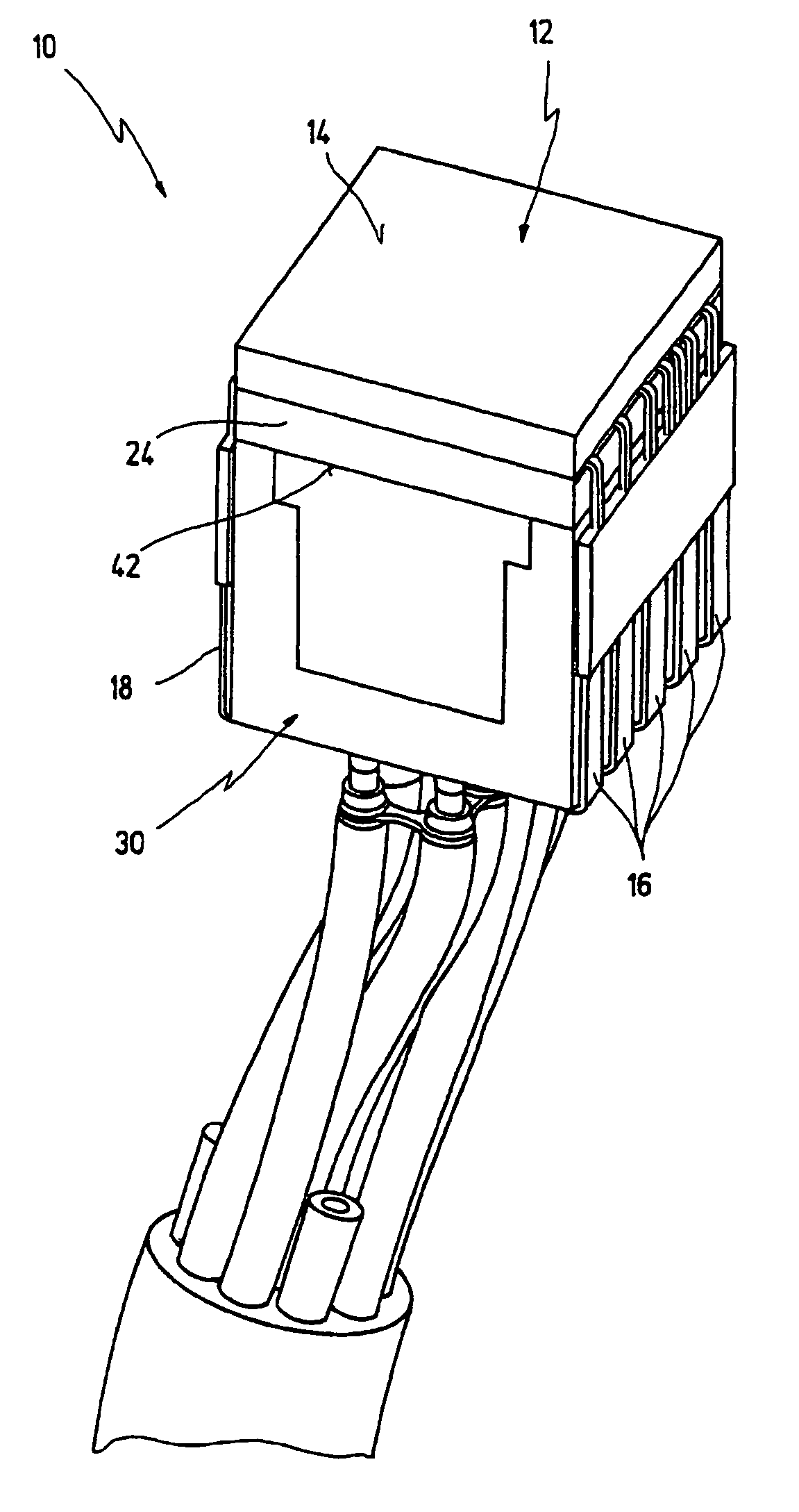
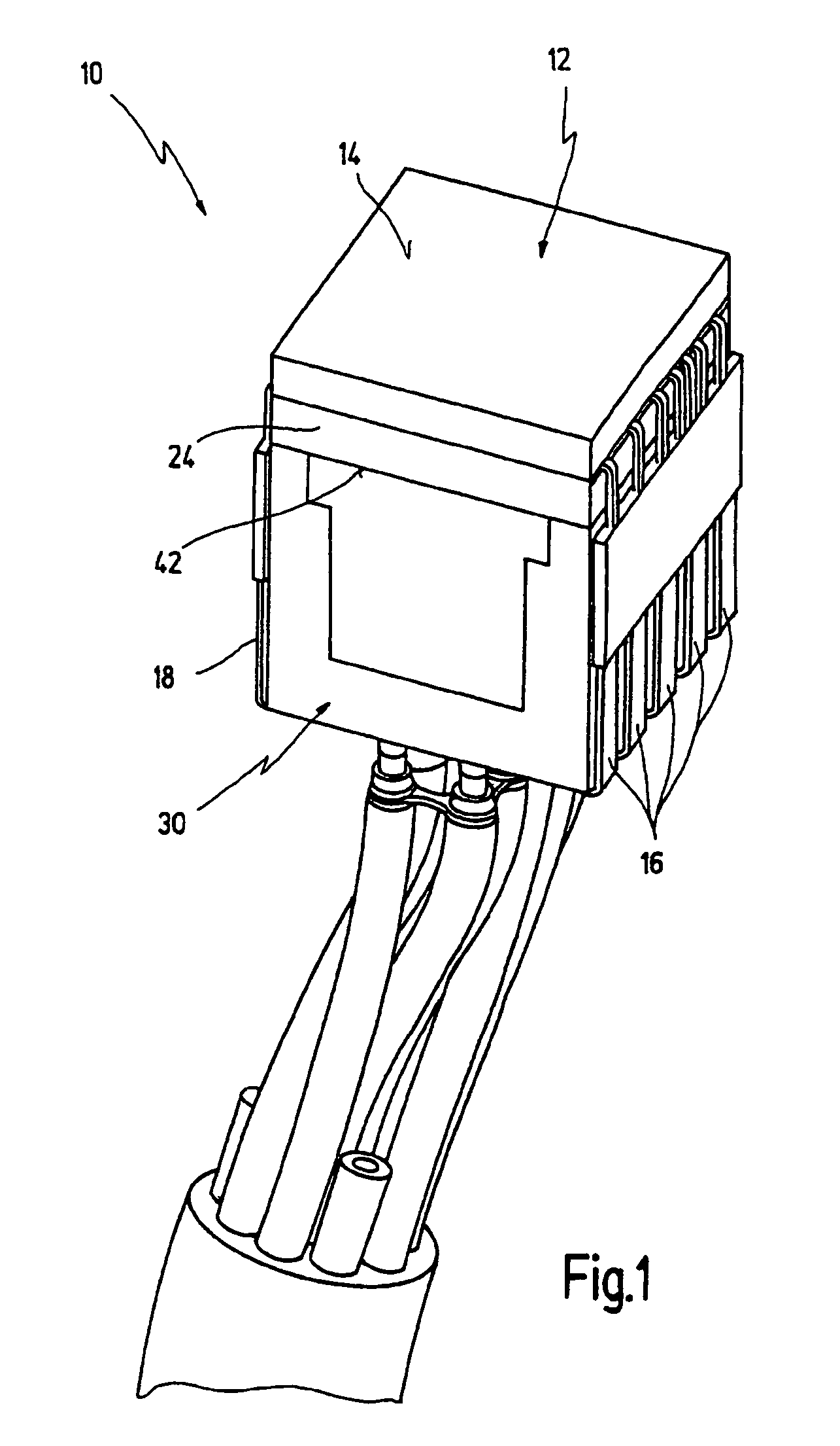
[0072]FIGS. 1 and 10 illustrate an image pick-up module provided with the general reference symbol 10 in its entirety and in the finished assembled state. Details of the image pick-up module 10 are illustrated in FIGS. 2 to 9.

[0073]The image pick-up module 10 is preferably used in an endoscope (not illustrated), in particular a video endoscope, or in a miniaturized camera. The image pick-up module 10 is an optoelectronic component in miniaturized form. It goes without saying that the illustrations in FIGS. 1 to 10 are greatly enlarged.

[0074]The image pick-up module 10 has an electronic image sensor 12 as first main component. The image sensor 12 has an outer side 14 at the light entry end, through which light enters the image sensor 12. An imaging optical system is connected upstream of the outer side 14 at the light entry end when the image pick-up module 10 is in use, for example in the state in which it is installed in an endoscope, in the distal tip thereof, in order to image an...


PUM


Abstract

The invention relates to an image pick-up module, in particular for an endoscope, comprising an electronic image sensor having a plurality of contact fingers that are arranged in two rows on opposite sides and each have a length, and a circuit board, to which the contact fingers are electrically contact-connected, the circuit board having at least three sections which are connected to one another in one piece and of which a first and a second section extend in a manner spaced apart from one another essentially transversely with respect to the image sensor and a third section extends essentially parallel to the image sensor, the image sensor being arranged at the end of the first and second sections which is remote from the third section, and at least one row of the contact fingers of the image sensor running along an outer side of the first or second section. The first section, the second section and the third section are connected to one another in an unarticulated manner, the length of the first section and / or of the second section is less than or equal to the length of the contact fingers and a space is present between the first, second and third sections of the circuit board, at least one electronic component for the control electronics of the image sensor being present in the said space.

Description

CROSS REFERENCE TO RELATED APPLICATION[0001]The present application claims priority of German patent application 10 2004 056 946.0 filed on Nov. 23, 2004.BACKGROUND OF THE INVENTION[0002]The invention relates to an image pick-up module, in particular for an endoscope or a miniature camera, comprising an electronic image sensor having a plurality of contact fingers that are arranged in two rows on opposite sides, and a circuit board, to which the contact fingers are electrically contact-connected.[0003]The invention furthermore relates to a method for assembly of an image pick-up module.[0004]An electronic image pick-up module is generally used in video recording technology. Besides the use in video cameras, such electronic image pick-up modules are used, in as miniaturized a design as possible, in particular also in endoscopes for technical or medical purposes. Such an endoscope or video endoscope is disclosed for example in U.S. Pat. No. 5,754,313.[0005]An image pick-up module gene...

Claims


Application Information

Patent Timeline
Patent Type & Authority Patents(United States)
IPC IPC(8): A61B1/00H04N9/47A62B1/04
CPCA61B1/0011A61B1/00124A61B1/051H01L27/14618H01L27/14636H01L27/14683H04N5/2253A61B1/05H01L2924/0002H04N2005/2255H01L2924/00H04N23/555H04N23/54
Inventor AYRENSCHMALZ, ROBERT
Owner KARL STORZ GMBH & CO KG
Why Eureka
Try Eureka