Tool for deciphering the depths or cuts on a key from the lock itself

a key and depth technology, applied in the field of deciphering the depths or cuts can solve the problem of the lock getting trapped in the lock, and achieve the effect of solving the problem of the depth or cut on the key from the lock itsel

Inactive Publication Date: 2011-03-01
CAPEHART KEITH DANIEL
View PDF6 Cites 3 Cited by
  • Summary
  • Abstract
  • Description
  • Claims
  • Application Information

AI Technical Summary

Benefits of technology

[0011]A reader that works by modifying a key blank by cutting a slot down the length on it so that a slide can be inserted into the lock with the modified key blank and measure the height of each wafer. This measurement translates into the cut depth that a key would need to be to operate that particular lock. Typically a lock has four depths of cuts on a key. With a slide tool for each depth you can accurately determine what depth the cut needs to be for that particular space on the key.

Problems solved by technology

When the insertion / release tool is removed the wafer will get trapped in a slot cut into the key.

Method used


Image

  • Tool for deciphering the depths or cuts on a key from the lock itself
  • Tool for deciphering the depths or cuts on a key from the lock itself
  • Tool for deciphering the depths or cuts on a key from the lock itself

Examples


Embodiment Construction

Number Description List

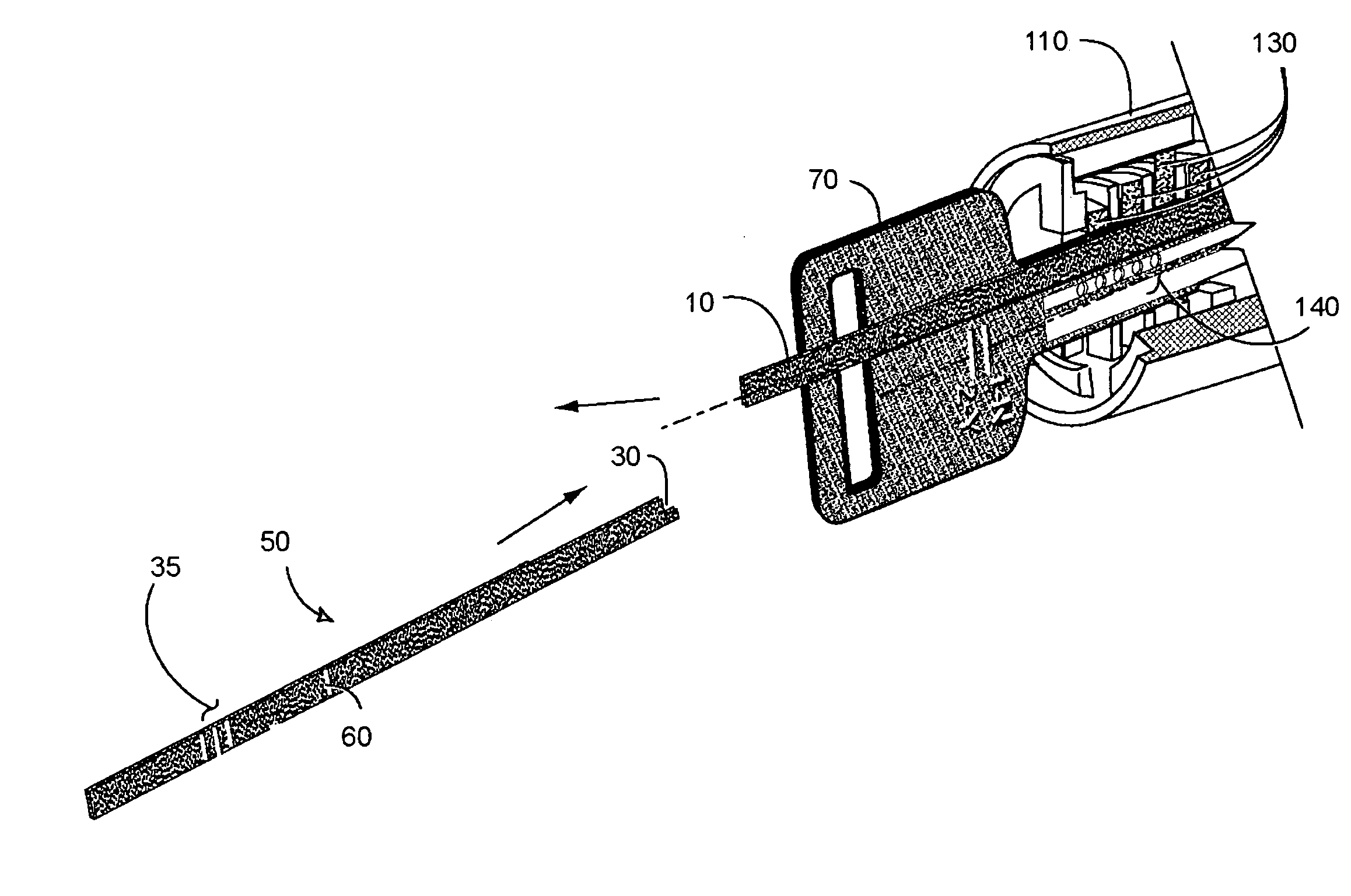
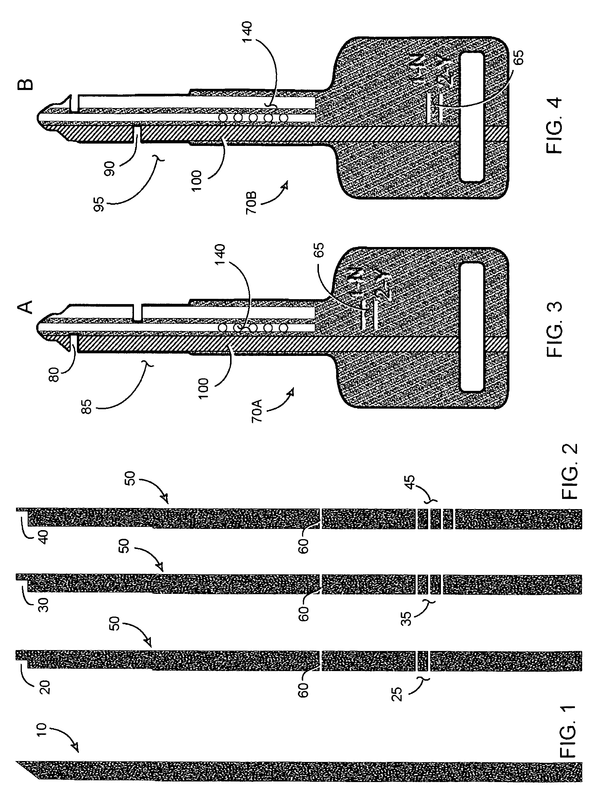
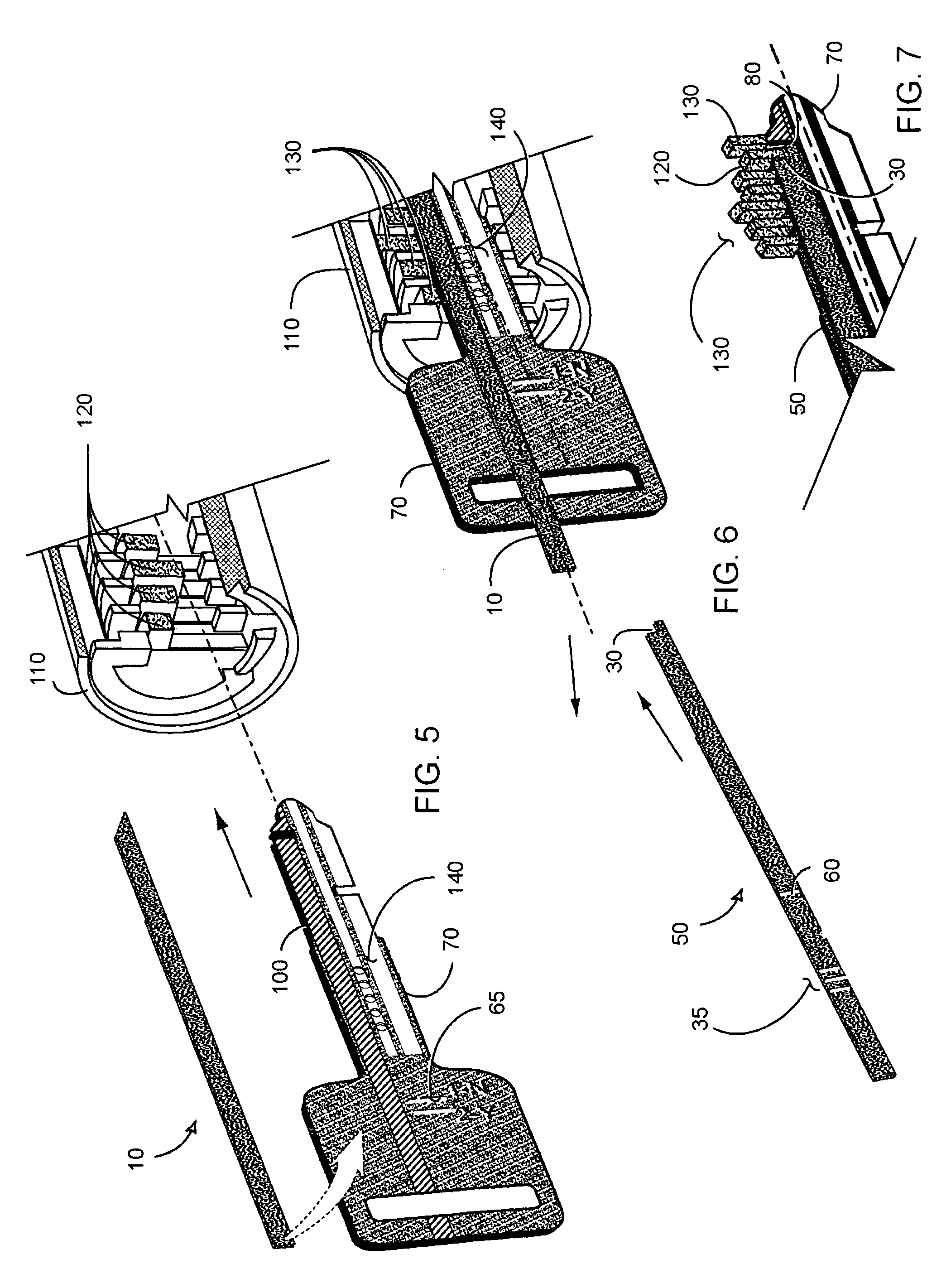
[0030]10 is a release and insertion tool.[0031]20 is a 2-depth gauge.[0032]25 is a 2-depth label or identifier.[0033]30 is a 3-depth gauge.[0034]35 is a 3-depth label or identifier.[0035]40 is a 4-depth gauge.[0036]45 is a 4-depth label or identifier.[0037]50 is a depth slot tool.[0038]60 is a depth slot tool measurement line.[0039]65 is a key measurement line pair, one for “NO” and one for “YES” for indicating the incorrect or the correct depth gauge depending upon the depth that the depth gauge is able to be inserted into a lock and whether or not it strikes or slides under a lock wafer in it's rest position.[0040]70 is a modified key blank.[0041]70A is a front side of a modified key blank.[0042]70B is a back side of the modified key blank.[0043]80 is a wafer slot for positioning at the inner wafers of a lock.[0044]85 is the active key side for the inner wafers of the lock.[0045]90 is a wafer slot for positioning at the outer wafers of the lock.[0046]95 is t...


PUM


Abstract

The objective of the invention is to allow the user to decipher the cuts (aka. depths) on a key from the lock without disassembling the lock. The current wafer lock readers on the market rely on a sensitive touch to operate and / or do not give the exact depths to recreate a key. Our wafer lock “reader” will give the exact depth of a cut, coming to a definite stop at the reading position for each cut on the key.

Description

FIELD OF THE INVENTION[0001]This invention relates to deciphering the depths or cuts on a key from the (wafer) lock itself, and more particularly concerns a system for determining how to make a key to replace a lost key for a specific tumbler or wafer lock.BACKGROUND OF THE INVENTION[0002]In cylinder locks of conventional design, a cylindrical plug having a key receiving slot or “keyway” bounded by straight upper and lower border surfaces, and having a first series of radially disposed channels communicating with said upper border surface is rotatably secured within a close fitting cylindrical bore in a housing having a second, matching series of channels, known as “pin chambers.” The pin chambers are in coaxial alignment with the first series of channels, and open upon said bore. The opposite extremities of the pin chambers, furthest from the bore, are closed. Each pin chamber confines a coil spring in abutment with said closed extremity, a driver pin and a tumbler pin. In some loc...

Claims


Application Information

Patent Timeline
Patent Type & Authority Patents(United States)
IPC IPC(8): G01B1/00E05B19/00E05B19/20
CPCG01B5/0018Y10T70/7797Y10T70/7802
Inventor CAPEHART, KEITH DANIEL
Owner CAPEHART KEITH DANIEL
Why Eureka
Try Eureka