Clothes dryer with thermal insulation pad

a technology of thermal insulation pad and dryer, which is applied in the field of clothes dryer, can solve the problem that the thermal insulation pad only requires limited thermal insulation capabilities, and achieve the effects of reducing the risk of fire, preventing the accumulation of combustible dust, and preventing the flow of oxygen

Inactive Publication Date: 2011-03-01
MABE CANADA
View PDF109 Cites 21 Cited by
  • Summary
  • Abstract
  • Description
  • Claims
  • Application Information

AI Technical Summary

Benefits of technology

[0004]The present invention relates to a clothes dryer having a thermal insulation pad that is placed within a confined space between the blower wheel housing and the dryer cabinet side wall closest thereto. By placing a thermal insulation pad strategically in this location, the pad fills up much of, if not all of, the volume of the confined space between the blower housing and the side wall of the cabinet closest thereto. Hence, the thermal insulation pad prevents the accumulation of combustible dust or lint over time in the confined space while also preventing the flow of oxygen to the confined space. Accordingly, the thermal insulation pad reduces the risk of a fire starting in the confined area of the dryer cabinet between the blower wheel housing and the adjacent side wall of the cabinet. Also, the thermal insulation pad acts as a barrier reducing the risk of fire, should one occur in the dryer drum or lower portion of the dryer cabinet, from spreading via the confined space between the dryer drum and lower portion of the dryer cabinet.
[0005]It should be understood that the thermal insulation pad utilized by the present invention may comprise any pad of material that has for example a plastic or woven material outer jacket with a fibrous filled material. The material does not have to resist high levels of heat because the blower fan housing does not rise to overly high temperatures during operation. Hence the thermal insulation pad only requires limited thermal insulation capabilities. In practice it has been found that padded material suitable for sound proofing works in this environment. Accordingly another advantage associated with a thermal insulation pad is that it provides some noise buffering or dampening by its placement in the confined space.

Problems solved by technology

Hence the thermal insulation pad only requires limited thermal insulation capabilities.

Method used


Image

  • Clothes dryer with thermal insulation pad
  • Clothes dryer with thermal insulation pad
  • Clothes dryer with thermal insulation pad

Examples


Embodiment Construction

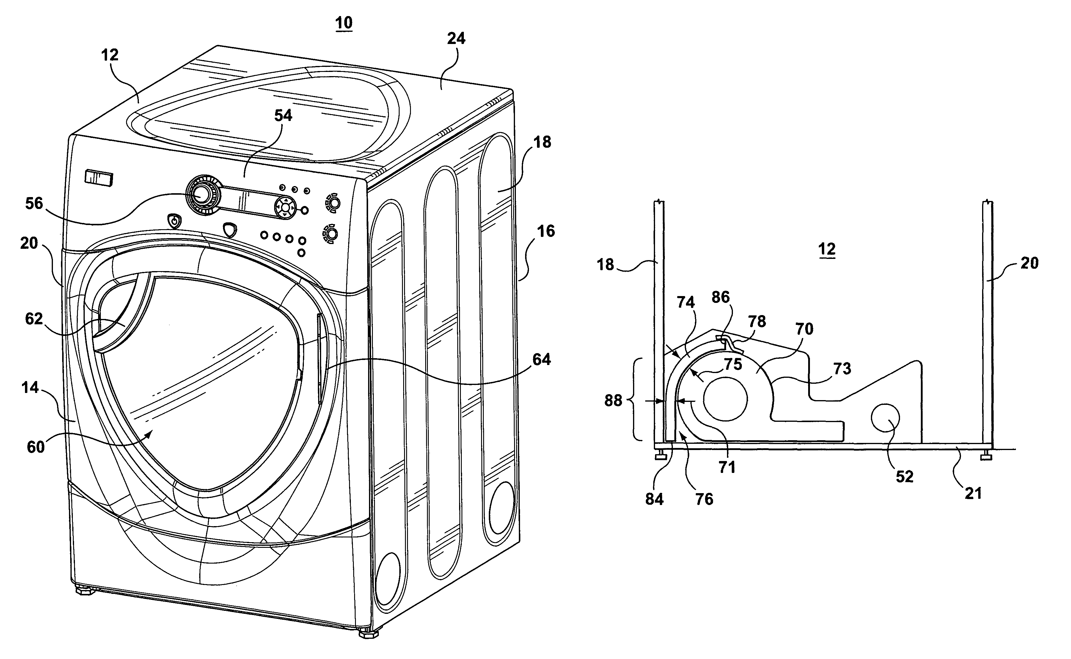
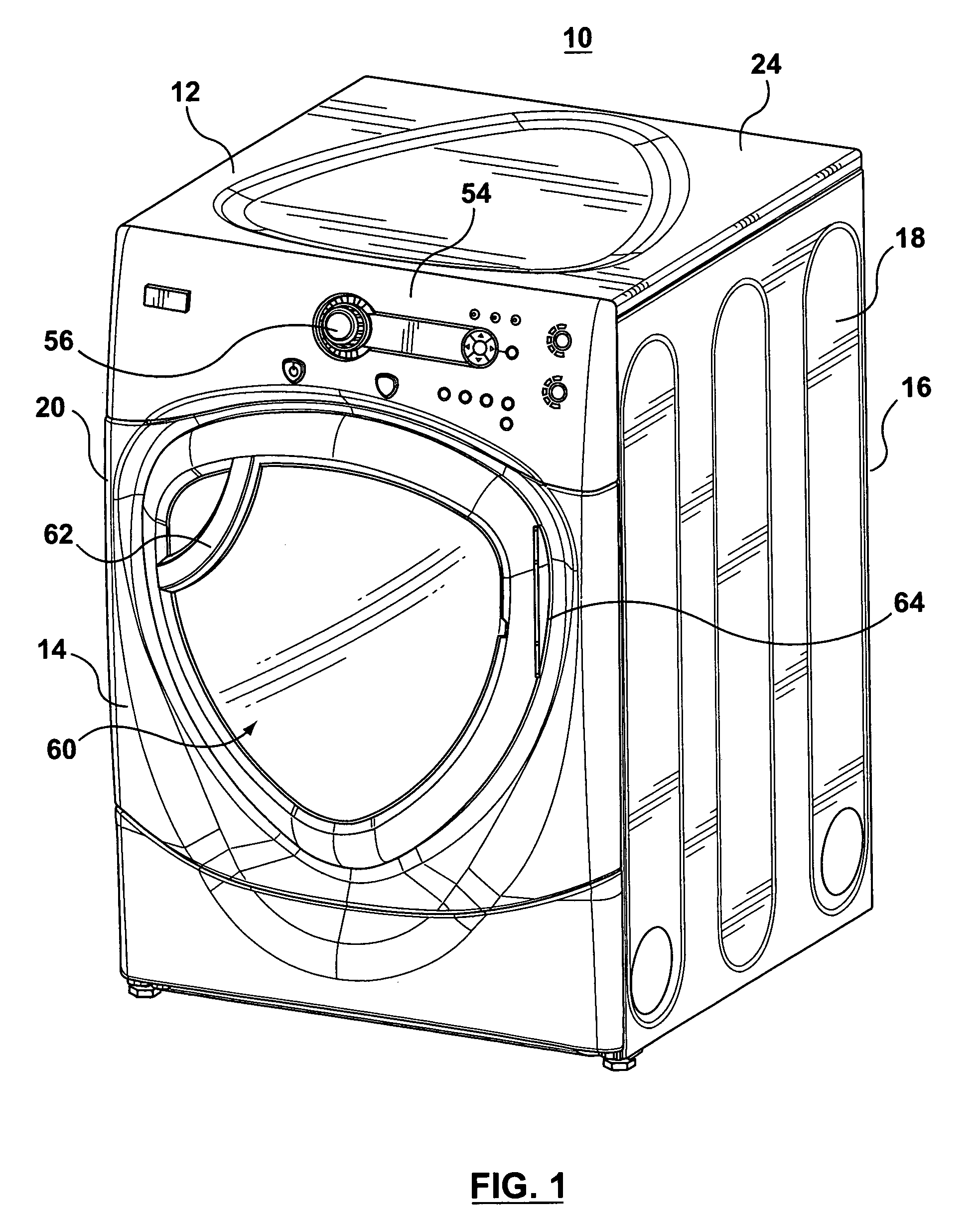
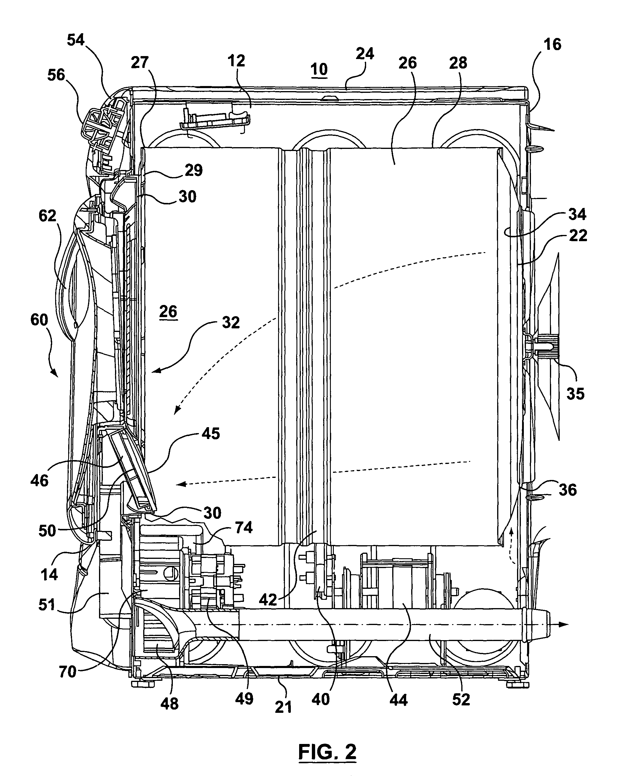
[0013]FIGS. 1 and 2 show perspective and side sectional views of an exemplary clothes dryer 10 that may benefit from the present invention. The clothes dryer 10 includes a cabinet or a main housing 12 having a front wall 14, a rear wall 16, a pair of side walls 18 and 20 spaced apart from each other by the front and rear walls, a floor 21 and a top cover 24. Within the housing 12 is a drum or container 26 mounted for rotation around a substantially horizontal axis. A motor 44 rotates the drum 26 about the horizontal axis through, for example, a pulley 40 and a belt 42. The drum 26 is generally cylindrical in shape, has an outer cylindrical wall 28, and has an open end 27 that typically comprises a metal ring 29 attached by welding to the drum 26 for reducing the diameter of the opening of the drum 26 to match a front bulkhead wall or front bearing 30. The bearing 30 further defines an opening 32 into the drum 26. Clothing articles and other fabrics are loaded into the drum 26 throug...


PUM


Abstract

A clothes dryer has a thermal insulation pad placed in a confined space in the dryer cabinet between the blower fan housing and the dryer cabinet side wall closest to the blower fan housing. The thermal insulation pad is press fit into the space so as to take up much of the volume of the confined space preventing the accumulation of dust or lint over time in the confined space while also preventing the flow of oxygen to the confined space. Accordingly, the thermal insulation pad reduces the risk of a fire starting in the confined area of the dryer cabinet between the blower wheel housing and the adjacent side wall of the cabinet. A thermal insulation pad also acts as sound insulation.

Description

FIELD OF THE INVENTION[0001]The present invention relates to a clothes dryer having a thermal insulation pad strategically placed in the dryer cabinet relative to the blower fan housing to reduce the risk of fire starting in this area of the dryer cabinet or spreading through this area between the dryer drum and the lower portion of the dryer cabinet.BACKGROUND OF THE INVENTION[0002]Clothes dryers for domestic use typically comprise a rotating drum in which clothes are tumbled as warm air moves through the drum. Airflow through the drum is induced by a centrifugal fan, or blower fan, located in an exhaust duct that has an opening facing into the front open end of the dryer drum. This opening is typically covered by a grill. The exhaust duct has a lint filter for trapping lint particles from continuing to flow through the exhaust duct. The blower fan is in airflow communication with this exhaust duct to draw air from the duct through the fan and out through a tangential duct which ai...

Claims


Application Information

Patent Timeline
Patent Type & Authority Patents(United States)
IPC IPC(8): F26B19/00
CPCD06F58/04D06F58/20
Inventor PRAJESCU, SILVIA IONELIARENZO, PASQUALE ANTONIO
Owner MABE CANADA
Why Eureka
Try Eureka