Electric power tool

a technology of electric power tools and power tools, applied in the field of hand tools, can solve problems such as inconvenience for consumers

Inactive Publication Date: 2011-03-01
MOBILETRON ELECTRONICS
View PDF12 Cites 21 Cited by
  • Summary
  • Abstract
  • Description
  • Claims
  • Application Information

AI Technical Summary

Benefits of technology

[0008]The primary objective of the present invention is to provide an electric power tool, which may switch various operation modes by one switch.
[0009]The secondary objective of the present invention is to provide an electric power tool, which provides fewer elements for impact mode and hammer mode.
[0008]The primary objective of the present invention is to provide an electric power tool, which may switch various operation modes by one switch.

Problems solved by technology

It is inconvenient to consumers.

Method used


Image

  • Electric power tool
  • Electric power tool
  • Electric power tool

Examples


Embodiment Construction

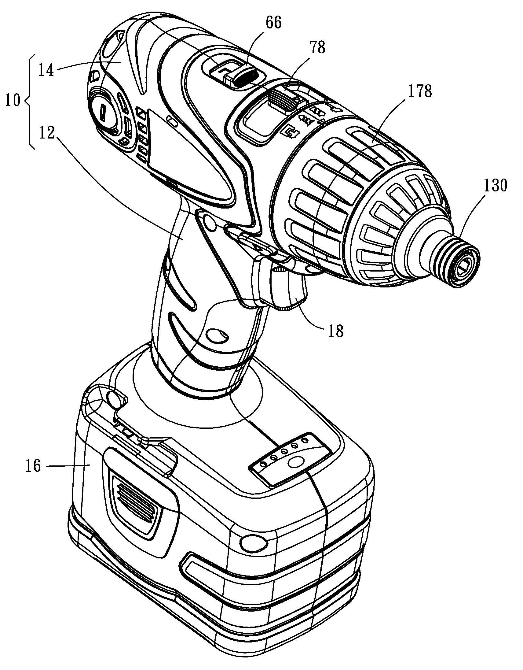
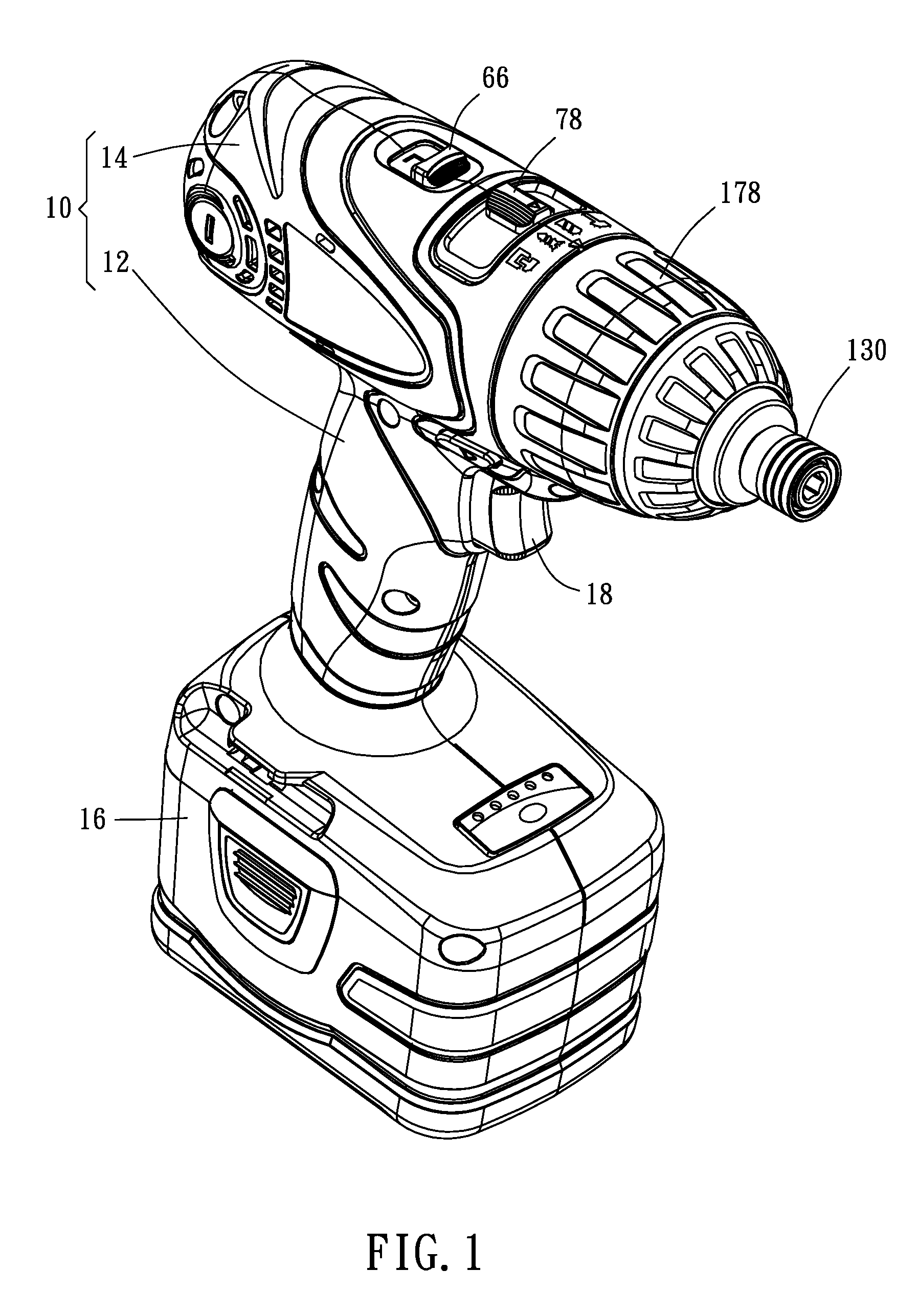
[0030]As shown in FIG. 1 to FIG. 4, an electric power toll of the preferred embodiment of the present invention includes a housing 10. The housing 10 has a handle 12 and a machine room 14. A battery 16 is mounted on a bottom of the handle 12, and a trigger 18 is provided on the handle 12. In the machine room 14, a motor 20, a planetary gear reduction mechanism 26, a switch mechanism 70, an impact mechanism 120, a hammer mechanism 142, a torque fixing mechanism 148, and a torque adjusting mechanism 162 are provided.

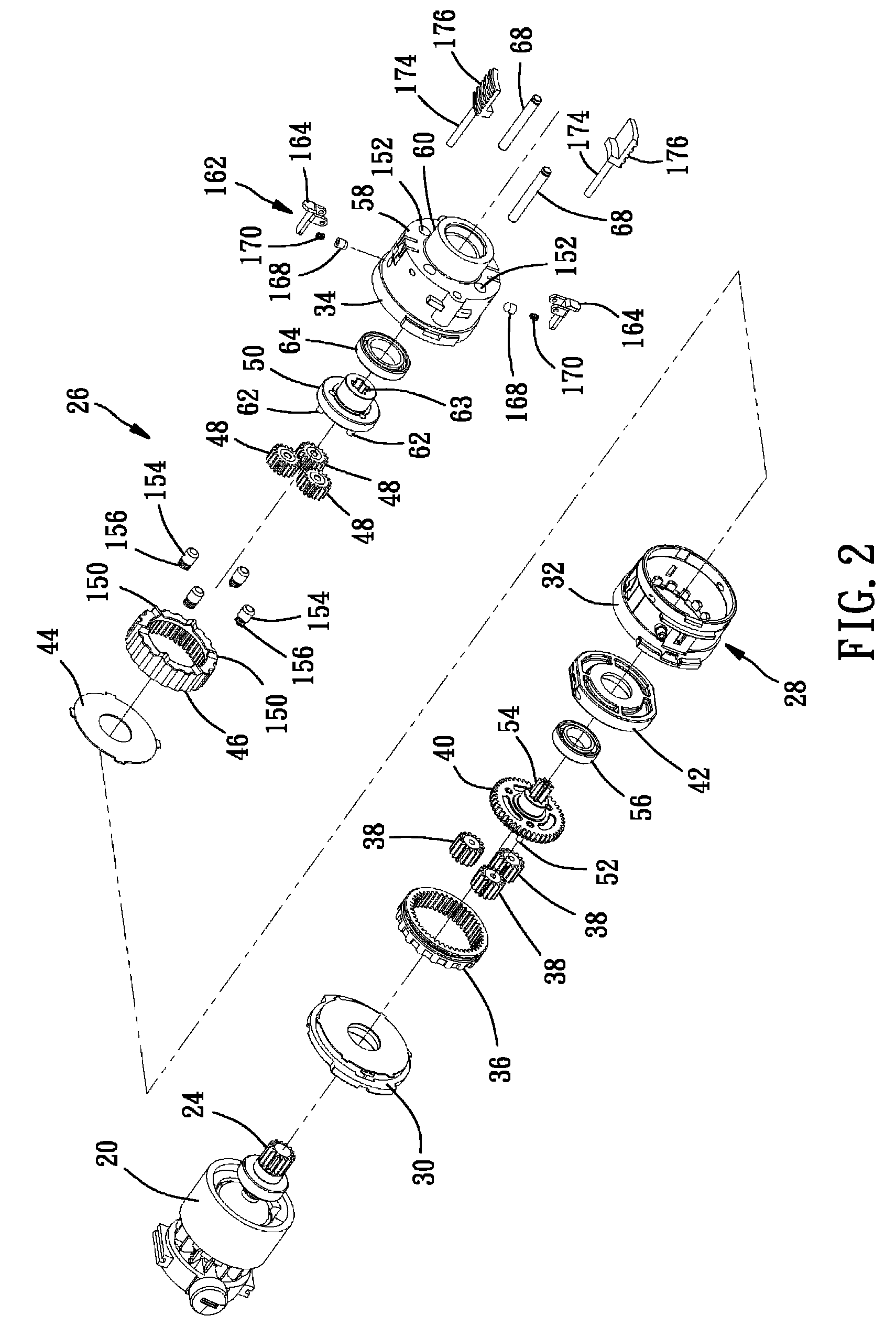
[0031]As shown in FIG. 4, the motor 20 is mounted in a rear of the machine room 14, which has a spindle 22 and a gear 24 on the spindle 24.

[0032]As shown in FIG. 2, the planetary gear reduction mechanism 26 includes a casing 28, in which a speed ring 36, three first planetary gears 38, a first rotary base 40, a support base 42, a pad 44, a torque ring 46, three second planetary gears 48, and a second rotary base 50. The casing 28 consists of a plate 30, a first housing 32,...


PUM


Abstract

An electric power tool includes a planetary gear reduction mechanism, a switch mechanism, an impact mechanism, a hammer mechanism, a torque fixing mechanism, and a torque adjusting mechanism. The switch mechanism includes a driving member, a first driven member, and a second driven member. A switching member is provided on the electric power tool and connected to the driving member to move it, and the driving member may drive the first driven member and the second driven member respectively to start or shut the impact mechanism and the hammer mechanism.

Description

BACKGROUND OF THE INVENTION[0001]1. Field of the Invention[0002]The present invention relates generally to a hand tool, and more particularly to an electric power tool capable of switching various operation modes by a single switch.[0003]2. Description of the Related Art[0004]Typically, a conventional electric power tool includes a motor, a planetary gear reduction mechanism, an impact mechanism, and a hammer mechanism. A shaft of the motor is connected to the planetary gear reduction mechanism to change the speed thereof, and the impact mechanism is connected to the planetary gear reduction mechanism. The conventional impact mechanism includes a shaft and an impact member. The shaft is driven by the planetary gear reduction mechanism. The shaft has slots thereon, in which balls are received. The impact member is fitted to the shaft through the balls. The impact member has two blocks on a top thereof. A spindle, which is connected to the shaft of the impact mechanism, has two arms i...

Claims


Application Information

Patent Timeline
Patent Type & Authority Patents(United States)
IPC IPC(8): B25D11/06B25D16/00
CPCB25B21/02B25D11/106B25D16/006B25F5/00B25F5/001B25D2250/255
Inventor TENG, CHENG-I
Owner MOBILETRON ELECTRONICS
Why Eureka
Try Eureka