Motor control device

a technology of motor control and control device, which is applied in the direction of electric generator control, dynamo-electric converter control, dynamo-electric gear control, etc., can solve the problems of complicated correction process, increased cost of the entire system equipped with the motor, and difficulty in detecting current values of two phases

Inactive Publication Date: 2011-03-01
SANYO ELECTRIC CO LTD
View PDF25 Cites 28 Cited by
  • Summary
  • Abstract
  • Description
  • Claims
  • Application Information

AI Technical Summary

Benefits of technology

[0022]More specifically, for instance, the motor control device further includes a coordinate converting portion for converting the two-phase specified voltage vector on the ab coordinates after the correction performed by the specified voltage vector correcting portion into a specified voltage vector on αβ coordinates having fixed α and β axes as its coordinate axes, and the magnetic flux estimating portion estimates the magnetic flux linkage based on the motor current and the specified voltage vector on the αβ coordinates.

Problems solved by technology

Although two current sensors (current transformers or the like) are usually used for detecting current values of two phases, the use of two current sensors causes an increase of cost of the entire system equipped with the motor.
However, if the maximum phase and an intermediate phase of voltage become close to each other, or if the minimum phase and the intermediate phase of voltage become close to each other, it is difficult to detect current values of two phases (note that description of the single shunt current detecting method including description of a reason why it becomes difficult to detect current values of two phases will also appear later with reference to FIG. 4 and the like).
If an applied voltage is low, in particular, the correction may be required for each of the three phases resulting in a complicated correction process.
Unless this is taken into account for making up the control system, the estimated magnetic flux will have an error.

Method used


Image

  • Motor control device
  • Motor control device
  • Motor control device

Examples


first example

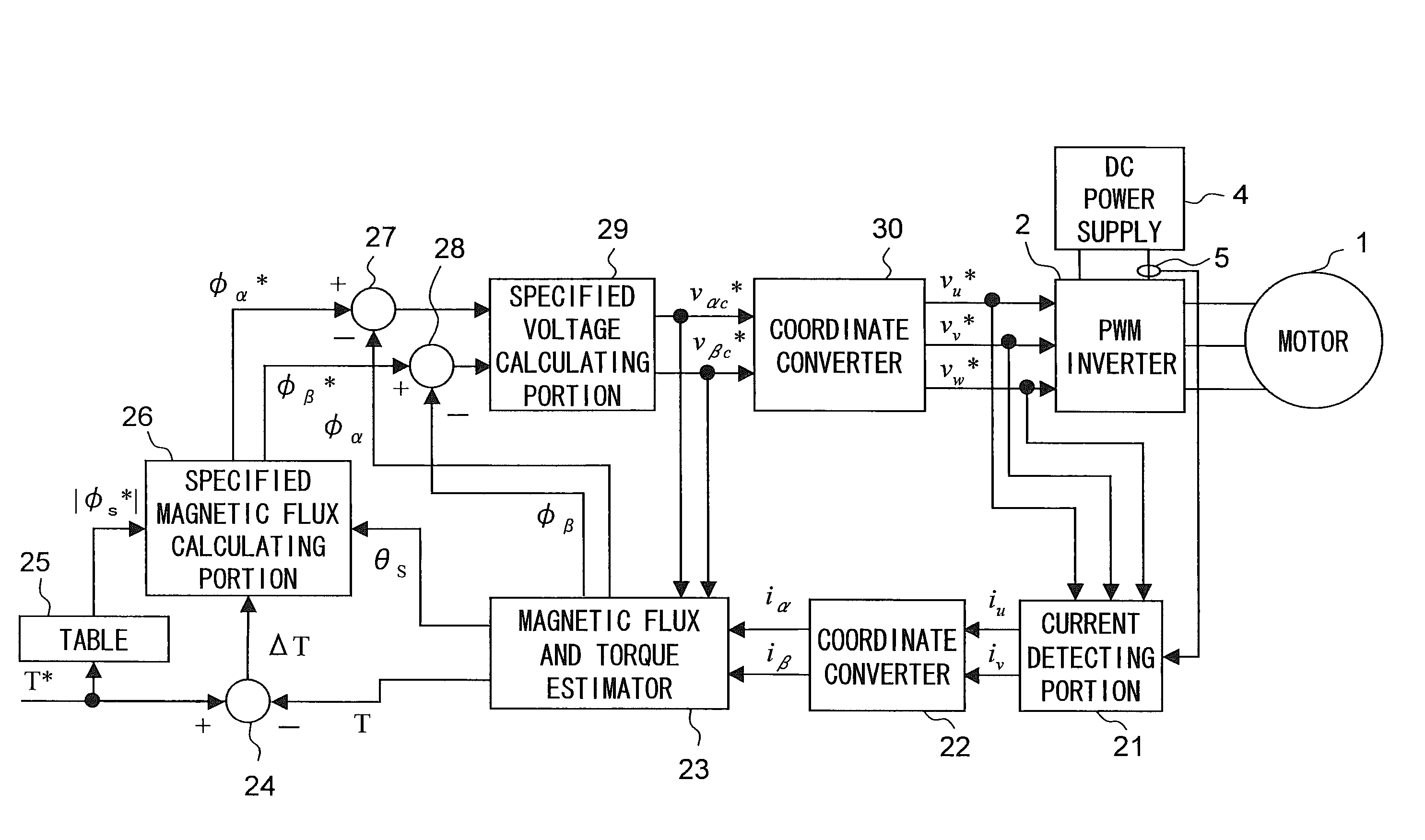
[0128]The first example will be described. FIG. 14 is a block diagram illustrating a structure of a motor driving system according to the first example. In the motor driving system shown in FIG. 14, so-called direct torque control is performed. If an interior permanent magnet motor or the like is used, magnetic flux of a permanent magnet or an inductance distribution may have harmonics in many cases. For instance, the magnetic flux of the permanent magnet linking with the U-phase armature winding traces a waveform of a sine wave with respect to a change in rotor phase ideally, but actually the waveform includes harmonics, which causes a distortion of an induction voltage (electromotive force) generated by rotation of the permanent magnet. In the same manner, a d-axis inductance and a q-axis inductance of the armature winding also include harmonics. It is known that such harmonics can cause a torque ripple.

[0129]When the vector control is performed so that the d-axis current and the ...

second example

[0164]Next, a second example will be described. The symbols and the like defined in the first example are also used in the second example. FIG. 18 is a block diagram showing a structure of the motor driving system according to the second example. In the motor driving system shown in FIG. 18, the vector control is performed by estimating a rotor position from an estimated value of the magnetic flux linkage.

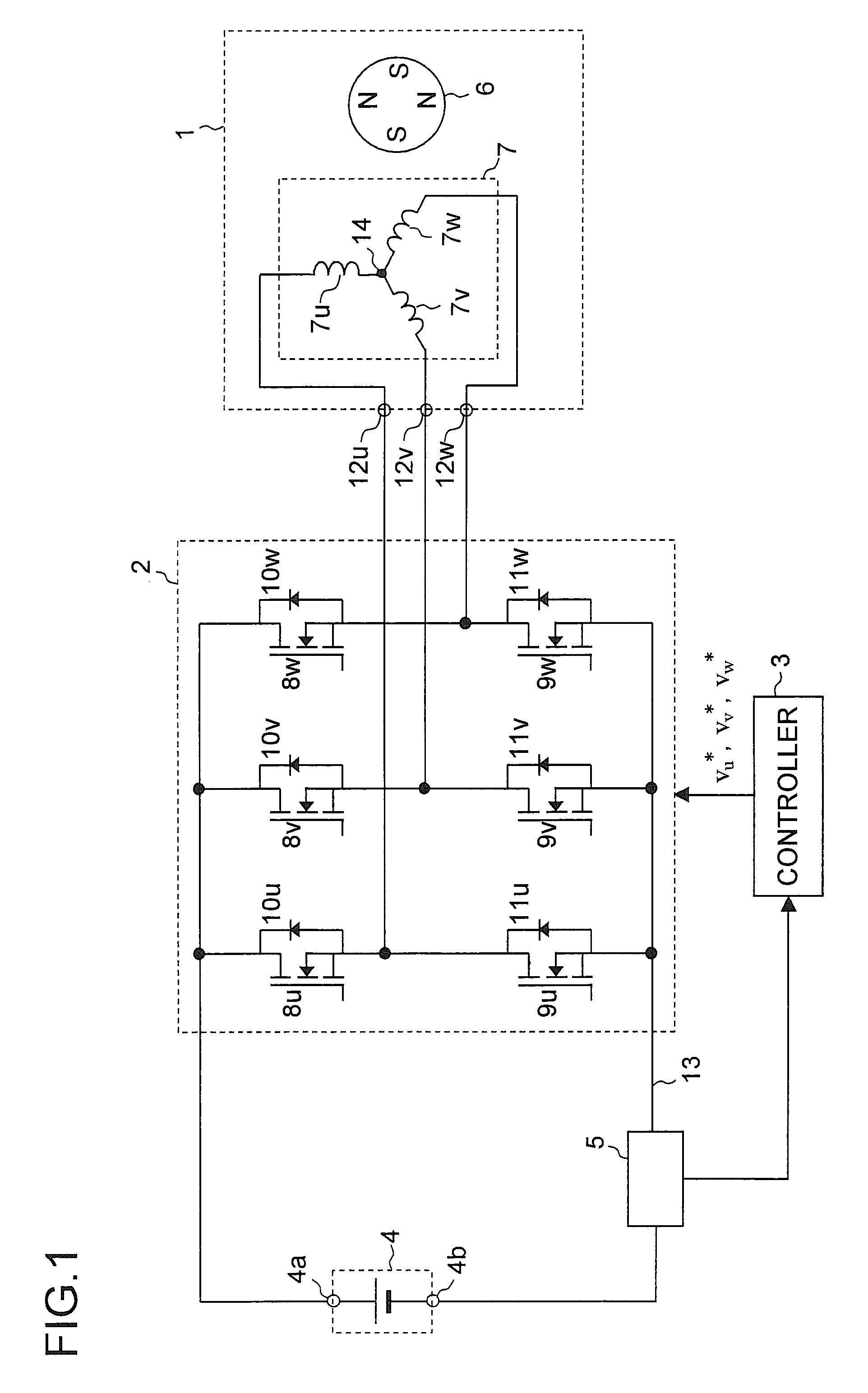
[0165]Prior to description of individual portions shown in FIG. 18, axes defined in the second example will be described, and calculation equations concerned with operations in the second example will be derived. FIG. 19 is referred to. FIG. 19 is an analytic model diagram of the motor 1. FIG. 19 shows the U-phase axis, the V-phase axis and the W-phase axis. Numeral 6a denotes a permanent magnet provided to the rotor 6 of the motor 1. In the rotating coordinate system rotating at the same speed as the magnetic flux of the permanent magnet 6a, the direction of the magnetic flux of t...


PUM


Abstract

A motor control device includes a motor current detector for detecting motor current flowing in a three-phase motor based on current flowing between an inverter driving the motor and a DC power supply, a specified voltage vector generating portion for generating a specified voltage vector indicating a voltage vector to which an applied voltage to the motor should follow based on a magnetic flux linkage of an armature winding of the motor, a specified voltage vector correcting portion for correcting the generated specified voltage vector, and a magnetic flux estimating portion for estimating the magnetic flux linkage based on the motor current and the specified voltage vector after the correction. The motor control device controls the motor via the inverter in accordance with the specified voltage vector after the correction.

Description

[0001]This nonprovisional application claims priority under 35 U.S.C. §119(a) on Patent Application No. 2007-195544 filed in Japan on Jul. 27, 2007, the entire contents of which are hereby incorporated by reference.BACKGROUND OF THE INVENTION[0002]1. Field of the Invention[0003]The present invention relates to a motor control device for driving and controlling a motor.[0004]2. Description of Related Art[0005]In order to control a motor by supplying three-phase AC power to the motor, it is necessary to detect current values of two phases (e.g., U-phase current and V-phase current) among three phases including U-phase, V-phase and W-phase. Although two current sensors (current transformers or the like) are usually used for detecting current values of two phases, the use of two current sensors causes an increase of cost of the entire system equipped with the motor.[0006]For this reason, there is proposed a conventional method in which bus current (DC current) between an inverter and a ...

Claims


Application Information

Patent Timeline
Patent Type & Authority Patents(United States)
IPC IPC(8): H02P21/14H02P6/06H02P6/08H02P27/06H02P6/16H02P21/00H02P21/06H02P21/09H02P21/22H02P23/30H02P25/026
CPCH02P21/10H02P21/14H02P21/148H02P27/08H02P21/141H02M1/0009
Inventor TOMIGASHI, YOSHIO
Owner SANYO ELECTRIC CO LTD
Why Eureka
Try Eureka