Systems and methods for object localization and path identification based on RFID sensing

a technology applied in the field of object localization and path identification, can solve the problems of limited system and method for localizing objects using rfid sensing, and typically do not allow for dynamic sensing reconfiguration

Active Publication Date: 2011-03-01
LUCOMM TECH
View PDF19 Cites 31 Cited by
  • Summary
  • Abstract
  • Description
  • Claims
  • Application Information

AI Technical Summary

Problems solved by technology

Systems and methods for localizing objects using RFID sensing tend to be limited to simple location determination and do not typically allow for dynamic sensing reconfiguration based on varying application demands.

Method used


Image

  • Systems and methods for object localization and path identification based on RFID sensing
  • Systems and methods for object localization and path identification based on RFID sensing
  • Systems and methods for object localization and path identification based on RFID sensing

Examples


Embodiment Construction

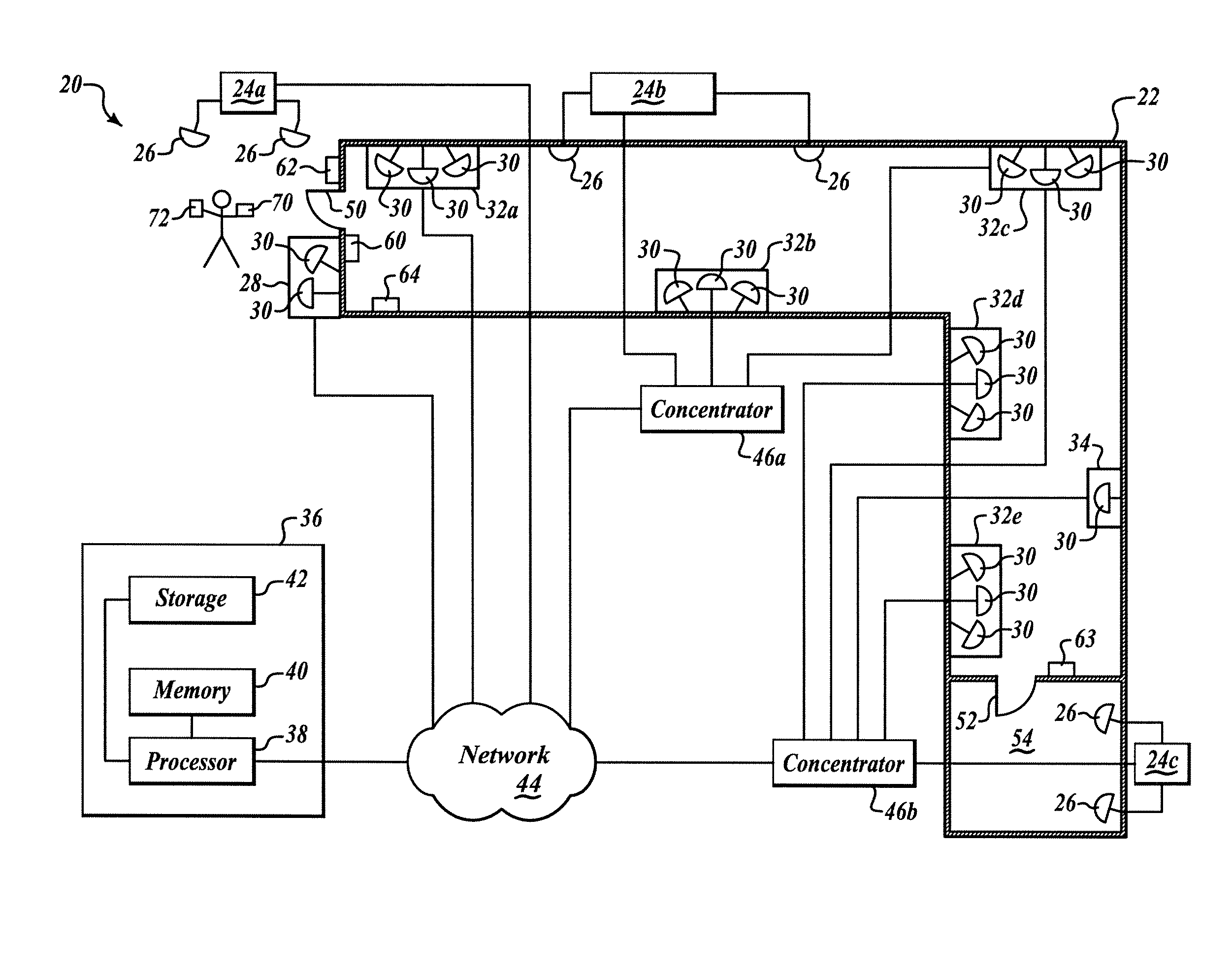
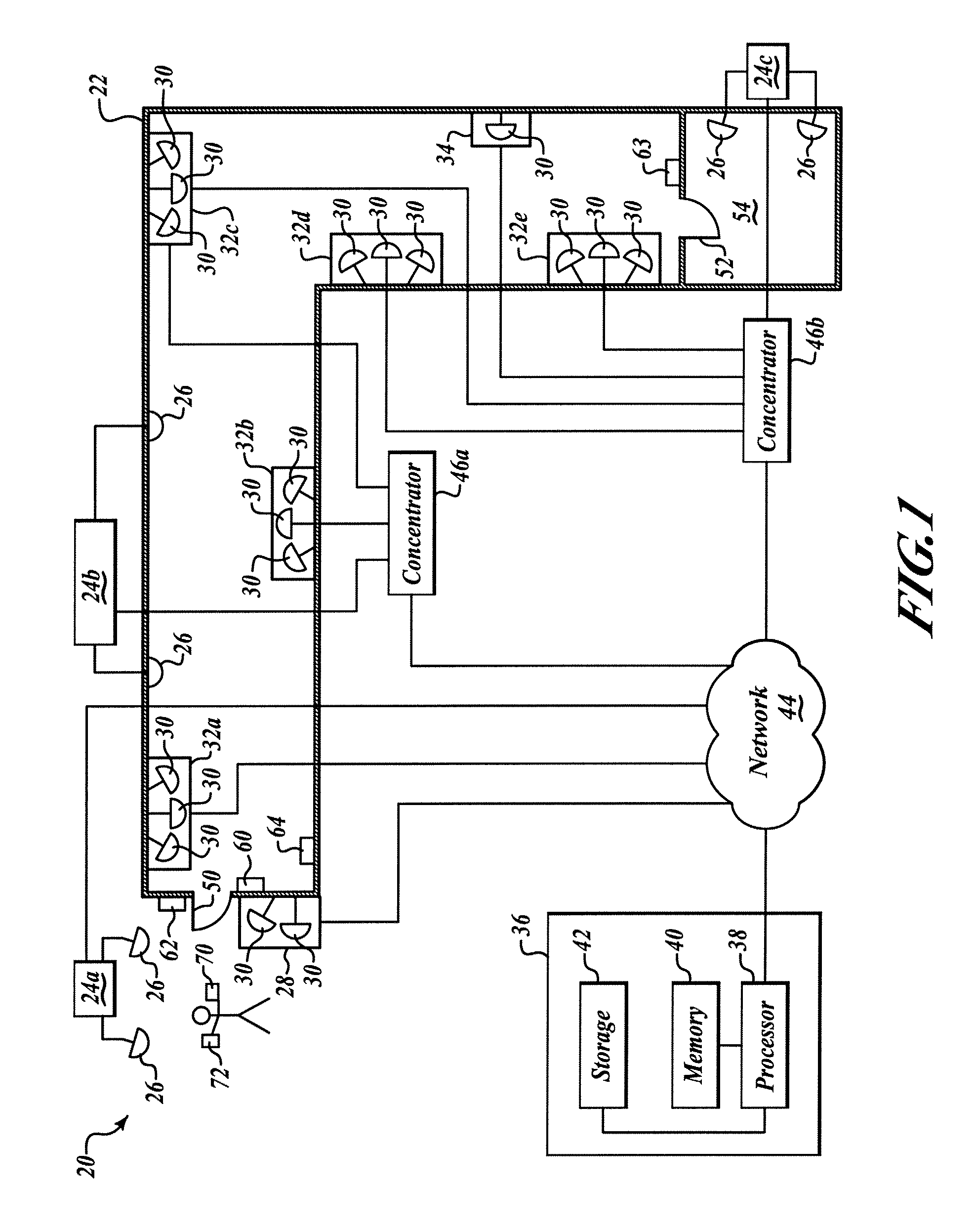
[0019]FIG. 1 is a block diagram showing an environmental view of a system 20 formed in accordance with an embodiment of the invention that is installed in a structure 22. Although a transceiver is preferred, a separate transmitter and receiver may alternatively serve as a transceiver within the scope of this invention.

[0020]The system 20 includes a plurality of radio frequency (RF) readers, each of which is associated with at least one interrogator. Each interrogator includes a transceiver and an antenna. Each interrogator (including transceiver and antenna) or only the interrogator's antenna may be external to the associated RF reader or embedded within the RF reader. The system 20 as shown includes three RF readers 24a, 24b, and 24c, each of which include two interrogators 26 that have antennas external to the RF readers 24a, 24b, and 24c. Transceiver components (not shown) of the interrogators 26 are embedded within the RF readers 24a, 24b, and 24c and are in signal communication...


PUM


Abstract

A networked radio frequency identification system includes a plurality of radio frequency identification (RFID) tag readers, a computer in signal communication with the RFID tag readers over a network, and a software module for storage on and operable by the computer that localizes RFID tags based on information received from the RFID tag readers using a network model having endpoints and oriented links. In an additional example, at least one of the RFID tag readers includes an adjustable configuration setting selected from RF signal strength, antenna gain, antenna polarization, and antenna orientation. In a further aspect, the system localizes RFID tags based on hierarchical threshold limit calculations. In an additional aspect, the system controls a locking device associated with an access point based on localization of an authorized RFID tag at the access point and reception of additional authorizing information from an input device.

Description

FIELD OF THE INVENTION[0001]This invention relates generally to object localization and path identification and, more specifically, to object localization and path identification based on radio frequency identification (RFID) sensing.BACKGROUND OF THE INVENTION[0002]Systems and methods for localizing objects using RFID sensing tend to be limited to simple location determination and do not typically allow for dynamic sensing reconfiguration based on varying application demands.SUMMARY OF THE INVENTION[0003]In one example, the present invention comprises a networked radio frequency identification system that includes a plurality of radio frequency identification (RFID) tag readers, a computer in signal communication with the RFID tag readers over a network, and a software module for storage on and operable by the computer that localizes RFID tags based on information received from the RFID tag readers using a network model having endpoints and oriented links.[0004]In accordance with a...

Claims


Application Information

Patent Timeline
Patent Type & Authority Patents(United States)
IPC IPC(8): H04B7/00
CPCG01S13/876G01S5/0278H04B5/0062G06K7/10366
Inventor CRISTACHE, LUCIAN
Owner LUCOMM TECH
Why Eureka
Try Eureka