Plastic optical element, nest structure, die, optical scan apparatus and image formation apparatus

a technology of optical elements and nest structures, applied in the field of plastic optical elements, can solve the problems of adversely affecting the optical performance, external defects, sink marks in molded plastic articles, etc., and achieve the effect of improving mass productivity and less optically harmful external defects

Active Publication Date: 2011-03-01
RICOH KK
View PDF16 Cites 3 Cited by
  • Summary
  • Abstract
  • Description
  • Claims
  • Application Information

AI Technical Summary

Benefits of technology

[0014]In view of solving the above problem, an object of the present invention is to provide a plastic optical element with improved mass productivity and less optically harmful external defects which can maintain the optical performance thereof at the current level, as well as to provide an optical scan apparatus including such plastic optical element, and an image formation apparatus incorporating such optical scan apparatus.

Problems solved by technology

When uneven resin temperature or local temperature distribution occurs in the die, or thermal contraction varies in the die, resulting in external defects such as sink marks in the molded plastic article.
However, this may cause another problem of inner distortion of the molded plastic article, especially at a portion in thin thickness, adversely affecting the optical performance thereof.
The air inflow locally decreases the temperature or adherence of the die, resulting in local thermal contraction, in other words, the sink marks in the molded plastic article as well as another external defect as air bubbles.
However, there is a drawback in the above-mentioned method that for molding the plastic optical element using the conventional nest structure which is composed of different members for the optical element body and the support portion, the occurrence of sink marks increases compared with using a general molding method.
The sink marks occur when compressed gas is supplied to the resin in the cavities due to the air flow into the joint surfaces between the members which causes local decrease in temperature or adherence of the die and results in local thermal contraction, or the sink marks.
However, there still remains a problem in this technique that the optical element body cannot be easily released from the nest structure.
In other words, it is not possible to continuously mold the plastic optical element in main scan direction which should be smoothly molded compared with sub scan direction.

Method used


Image

  • Plastic optical element, nest structure, die, optical scan apparatus and image formation apparatus
  • Plastic optical element, nest structure, die, optical scan apparatus and image formation apparatus
  • Plastic optical element, nest structure, die, optical scan apparatus and image formation apparatus

Examples


first embodiment

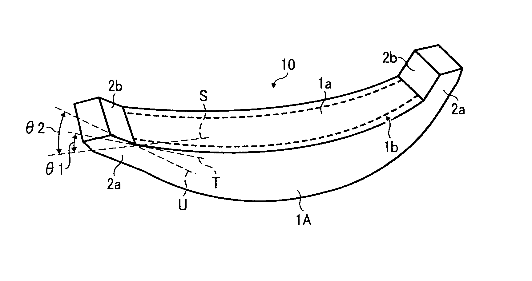
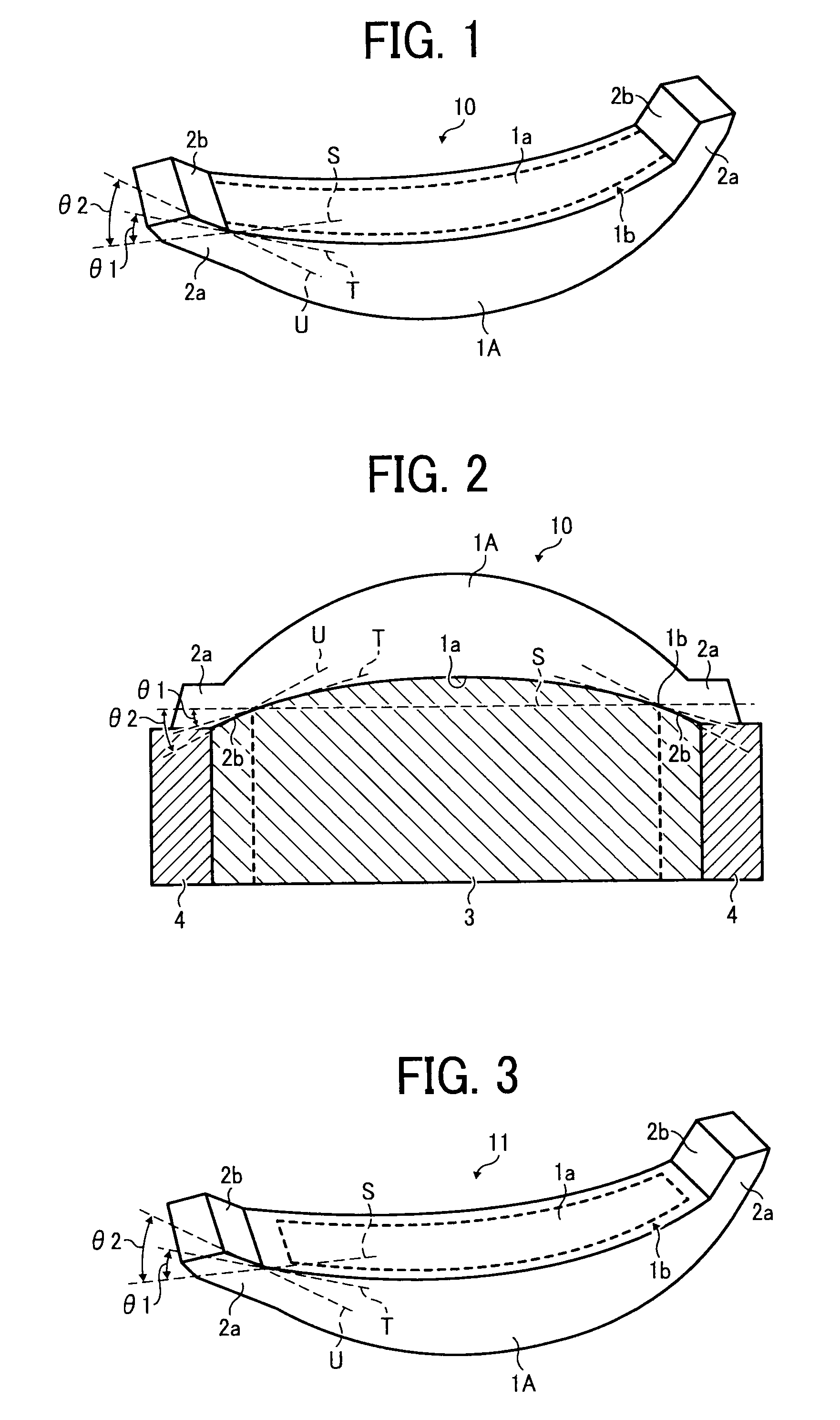
[0042]The first embodiment of the present invention will be described with reference to FIGS. 1, 2. FIG. 1 is a schematic perspective view of a plastic optical element according to the first embodiment. FIG. 2 is a vertical cross sectional view of an essential part of the plastic optical element molded in the nest structure of a die. Structure and operation of a plastic optical element 10 will be described using as an example an fθ lens as a component of an optical scan apparatus incorporated in a color laser beam printer.

[0043]The plastic optical element as an fθ lens comprises an optical element body 1A comprising a transfer surface 1b which includes at least one laser beam incident portion 1a of a concave shape and support portions 2a integrally formed with the optical element body at right and left ends thereof in the drawings. The plastic optical element 10 (11 to 14) has symmetric shapes relative to a central line so that only one part thereof will be described with reference ...

second embodiment

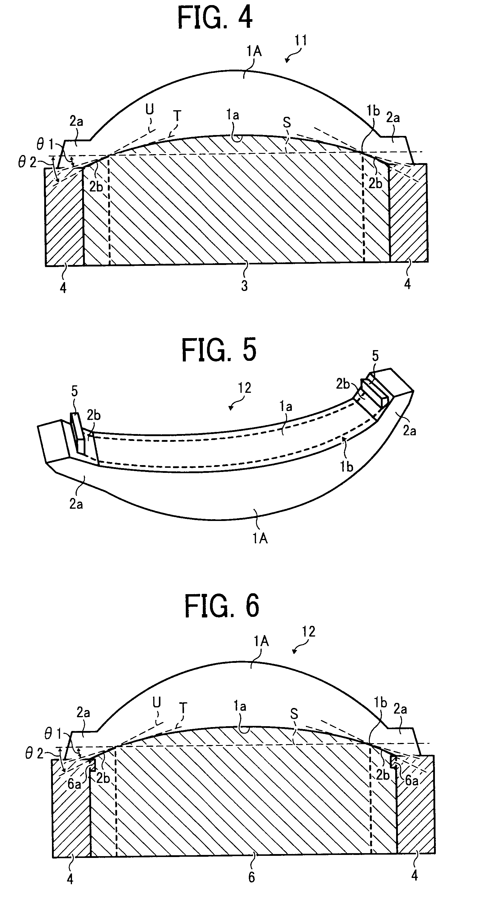
[0050]The second embodiment of the present invention will be described with reference to FIGS. 3, 4. FIG. 3 is a schematic perspective view of a plastic optical element according to the second embodiment. FIG. 4 is a cross sectional view of an essential part of the plastic optical element molded in the nest structure of a die. Structure and operation of a plastic optical element 11 will be described using as an example an fθ lens as a component of a later-described optical scan apparatus, as in the first embodiment.

[0051]The plastic optical element 11 according to the present embodiment is the same as that 10 in the first embodiment except that the optical element body 1A and the parts 2b of the support portions 2a are integrally molded in the same nest structure 3 in replace of the laser beam incident portion 1a and the parts 2b of the support portions 2a.

[0052]The plastic optical element 11 according to the present embodiment includes the support portions 2a which are each placed...

third embodiment

[0054]The third embodiment of the present invention will be described with reference to FIGS. 5, 6. FIG. 5 is a schematic perspective view of a plastic optical element according to the third embodiment. FIG. 4 is a cross sectional view of an essential part of the plastic optical element molded in the nest structure of a die. Structure and operation of a plastic optical element 12 will be described using as an example an fθ lens as a component of a later-described optical scan apparatus, as in the first embodiment.

[0055]The plastic optical element 12 according to the present embodiment is the same as that 10 in the first embodiment except that the right and left support portions 2a each include a rib 5 and that a nest structure 6 provided with concavities 6a for molding the ribs 5 is used in replace of the nest structure 3.

[0056]The feature of the plastic optical element 12 lies in that the laser beam incident portion 1a, the parts 2b of the support portions 2a, and the ribs 5 are mo...


PUM


Abstract

A plastic optical element is provided, which includes an optical element body having a transfer surface which includes at least one laser beam incident portion of a concave shape, and a support portion connected with the optical element body, in which the support portion is disposed in a direction of a tangent line at an end of the transfer surface, and the optical element body and a part of the support portion are molded in the same nest structure.

Description

CROSS-REFERENCE TO RELATED APPLICATIONS[0001]The present application is based on and claims priority from Japanese Patent Application No. 2007-239924, filed on Sep. 14, 2007, the disclosure of which is hereby incorporated by reference in its entirety.BACKGROUND OF THE INVENTION[0002]1. Field of the Invention[0003]The present invention relates to a plastic optical element used in an optical imaging system such as a laser digital copier, a laser printer, or a facsimile machine as well as an optical device such as a video camera. In particular, it relates to a plastic optical element made of a molded plastic article such as a plastic scan lens with a precise mirror face and a large, uneven thickness, and it relates to a nest structure for use in molding such plastic optical element, a die, an optical scan apparatus including the plastic optical element, and an image formation apparatus including the optical scan apparatus.[0004]2. Description of Related Art[0005]Heretofore, optical ele...

Claims


Application Information

Patent Timeline
Patent Type & Authority Patents(United States)
IPC IPC(8): G02B3/00
CPCB29D11/00432G02B7/022G02B13/0005
Inventor HAYASHI, EIICHIAOKI, KANIWAMATSU, AKIHIROTAKAHASHI, GO
Owner RICOH KK
Why Eureka
Try Eureka