
Operating time reducing method, operating time reducing apparatus, program and component mounter

a technology of operating time reducing and component mounting, which is applied in the direction of electric programme control, program control, instruments, etc., can solve the problem of difficult to determine the optimal mounting order of components within a practical time, and achieve the effect of optimal component mounting order

Inactive Publication Date: 2011-03-01
PANASONIC CORP
View PDF52 Cites 23 Cited by
  • Summary
  • Abstract
  • Description
  • Claims
  • Application Information

AI Technical Summary

Benefits of technology

"The present invention provides an operating time reducing method for a component mounter that mounts components onto a board. The method involves identifying an operation loss, selecting a processing procedure to reduce the operating time of the component mounter, and executing the selected processing procedure. The method allows for the determination of an optimal component mounting order within a practical time, while also addressing the issue of disorder in the movement between mounting points. The processing procedure can be changed based on the type of operation loss that affects the component mounting time. The technical effect of the invention is to provide an efficient and effective method for determining the optimal component mounting order in a practical time."

Problems solved by technology

However, in a round robin method in which all possible component mounting orders are generated and then the optimal component mounting order is acquired, the processing time necessary for determining the optimal component mounting order increases as the number of mounting points for the components increases, so that it is difficult to determine the optimal component mounting order within a practical time.

Method used


Image

  • Operating time reducing method, operating time reducing apparatus, program and component mounter
  • Operating time reducing method, operating time reducing apparatus, program and component mounter
  • Operating time reducing method, operating time reducing apparatus, program and component mounter

Examples


Embodiment Construction

[0303]A component mounting system according to an embodiment of the present invention is described below with reference to the drawings.

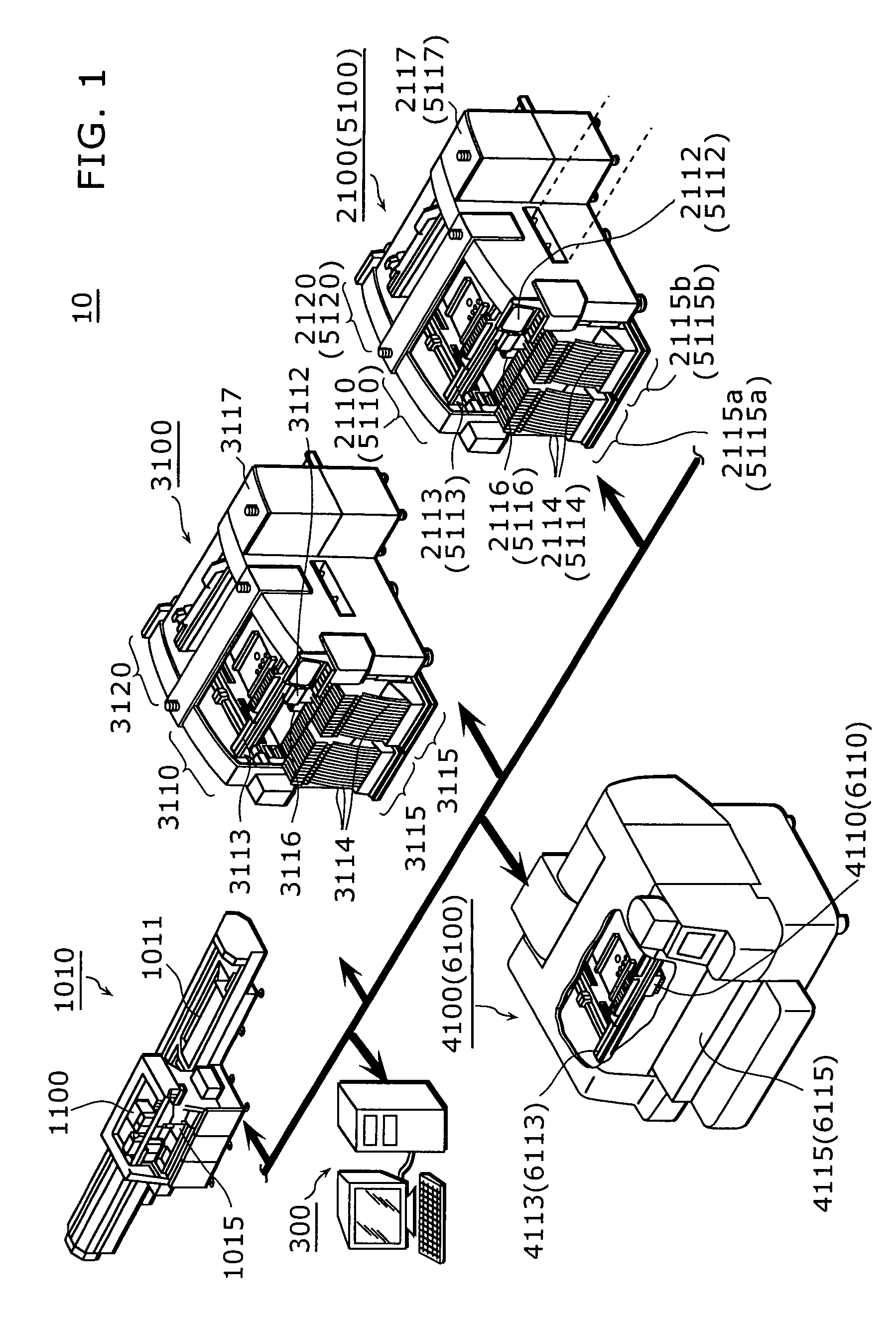
[0304]FIG. 1 is an external appearance view showing a configuration of a component mounting system according to the present embodiment.

[0305]A component mounting system 10 is a system in which a mounting order for mounting components onto a board is determined and the components are mounted onto the board in accordance with the determined mounting order. The component mounting system 10 includes a component mounter 1010, a component mounter 3100, a component mounter 2100, a component mounter 5100, a component mounter 4100, a component mounter 6100, and an operating time reducing apparatus 300.

[0306]The component mounters 1010, 3100, 2100, 5100, 4100 and 6100 are apparatuses that mount components onto a board. Detailed configuration of each component mounter is described later.

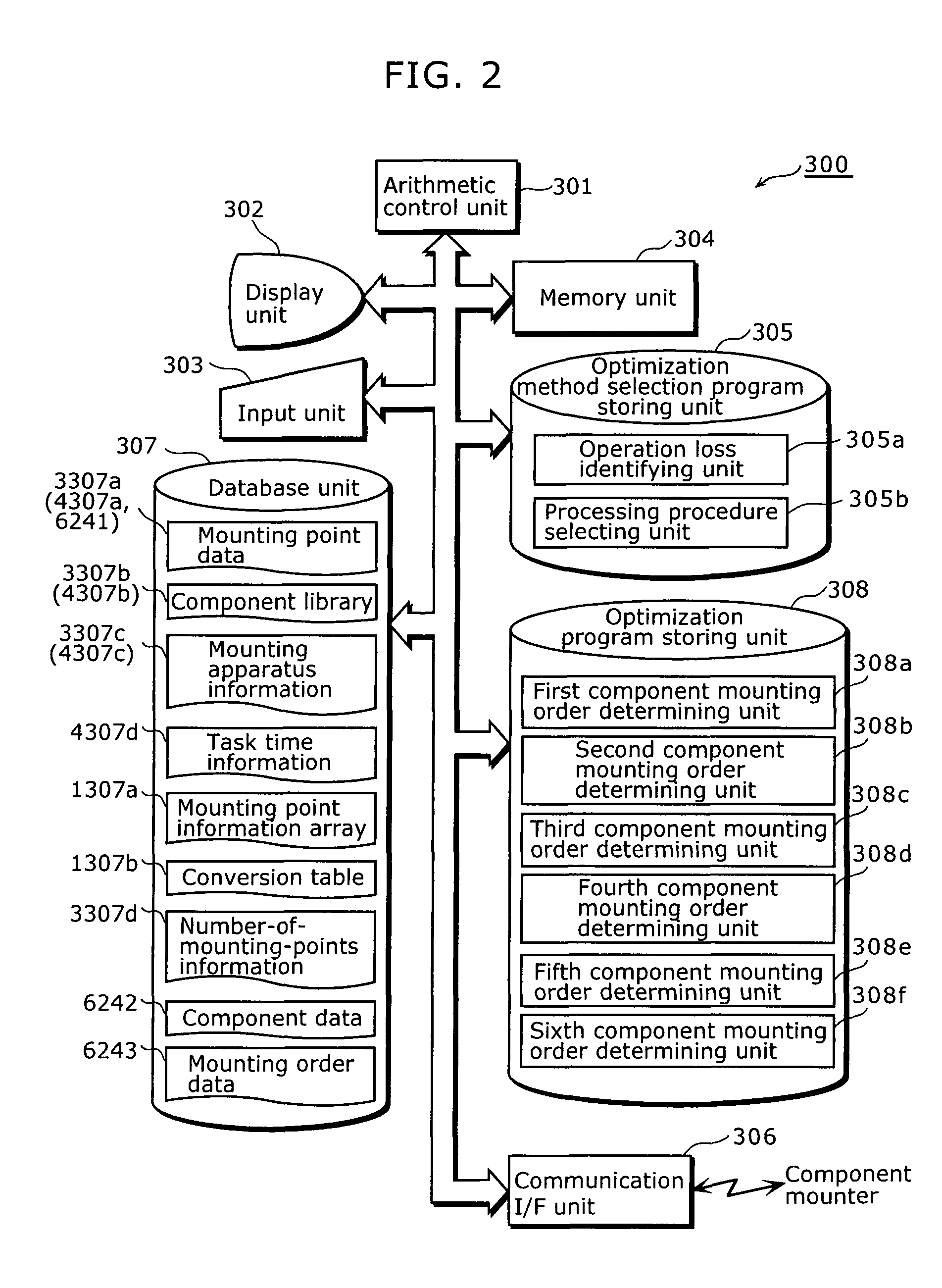
[0307]FIG. 2 is a functional block diagram showing a configuration of an o...


PUM

PropertyMeasurementUnit
view field sizeaaaaaaaaaa
mounting timeaaaaaaaaaa

Abstract

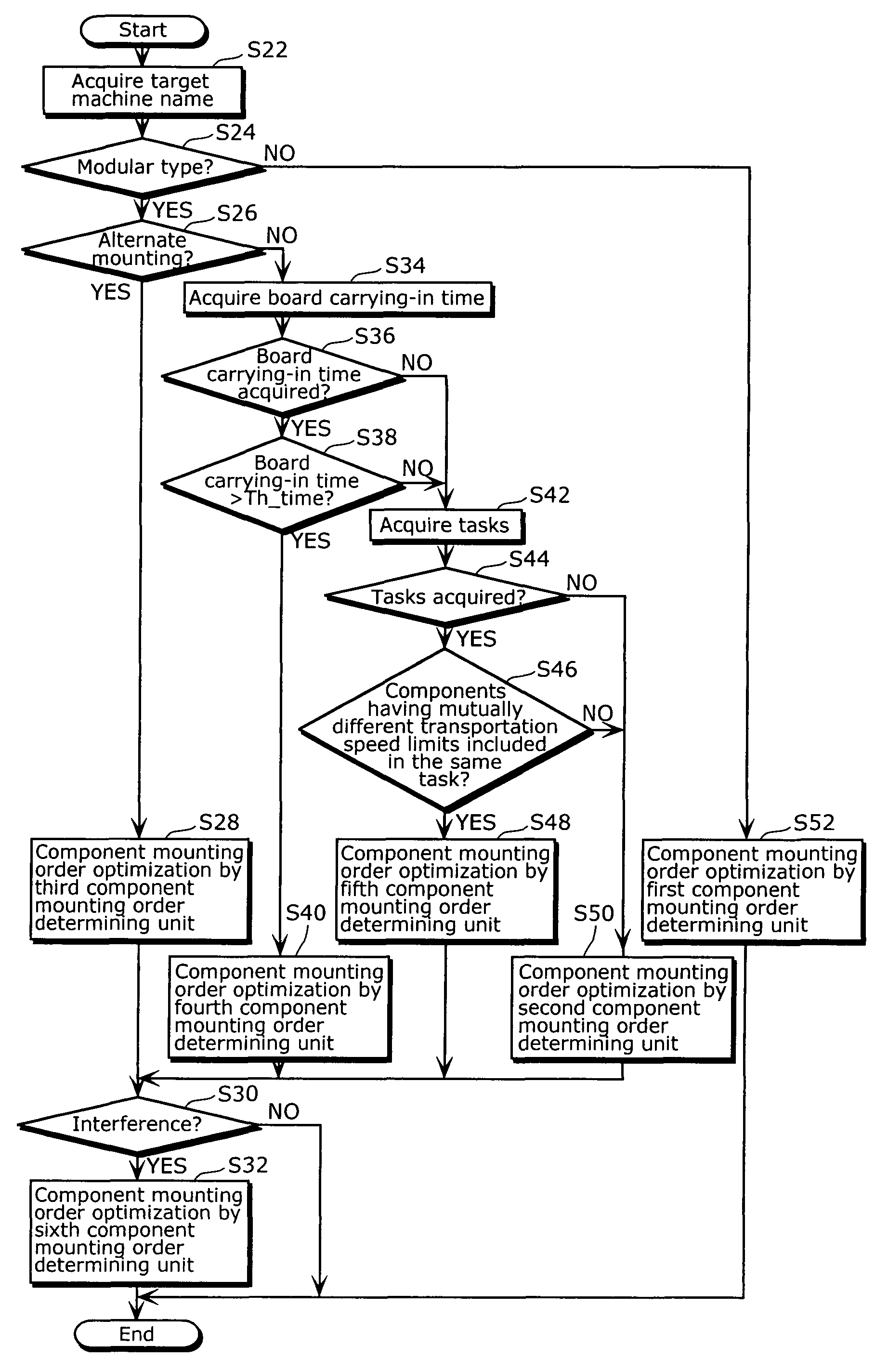
An operating time reducing method in which a processing procedure of a component mounting order determination method can be changed depending on the type of an operation loss that affects a component mounting time for mounting components onto the board is an operating time reducing method for a component mounter, wherein the method includes: an operation loss identifying step of identifying an operation loss to be resolved in the component mounter; a processing procedure selecting step of selecting, based on the identified operation loss, a processing procedure for reducing an operating time of the component mounter; and a processing procedure executing step of executing the selected processing procedure.

Description

TECHNICAL FIELD[0001]The present invention relates to an operating time reducing method for a component mounter that mounts components onto a board.BACKGROUND ART[0002]In component mounting onto a board performed by a component mounter, the mounting order for the components needs be determined before the component mounting. In a component mounting order determination method, the mounting order is determined with the aim of minimizing the time duration from the start of mounting of components until the completion of mounting of all components. However, in a round robin method in which all possible component mounting orders are generated and then the optimal component mounting order is acquired, the processing time necessary for determining the optimal component mounting order increases as the number of mounting points for the components increases, so that it is difficult to determine the optimal component mounting order within a practical time.[0003]Thus, as a method for determining ...

Claims


Application Information

Patent Timeline
Patent Type & Authority Patents(United States)
IPC IPC(8): G05B13/02G06F19/00
CPCH05K13/08Y10T29/53174Y10T29/4913Y10T29/53191H05K13/085H05K13/0853H05K13/04
Inventor MAENISHI, YASUHIROKONISHI, CHIKASHIYAMASAKI, AKIHITOKURIBAYASHI, TAKESHI
Owner PANASONIC CORP
Learn More