
Pergola having posts, beams, joists, strips, clips, and internal support stiffeners

a pergola and post technology, applied in the direction of girders, joists, sunshades, etc., can solve the problems of increasing the difficulty of a proper and user-friendly assembly, requiring costly annual maintenance, and previous structures taking a long time to install with quality structural components

Inactive Publication Date: 2011-03-08
LEINES RICHARD
View PDF35 Cites 34 Cited by
  • Summary
  • Abstract
  • Description
  • Claims
  • Application Information

AI Technical Summary

Problems solved by technology

Such shade structures (hereinafter pergolas) are exposed to the environment and often need regular annual maintenance that is costly as well as a nuisance.
Plastic, wood, composite, and metal materials, for example, have been used in the past for the construction of pergolas, but the method of connection and layout requirements of such pergolas increase the difficulty for a proper and user-friendly assembly.
Previous structures took a long time to install with quality structural components.
Also the components did not attach sequentially and uniformly.
This arrangement is very limited due to its archaic bolt-using installation approach, which is complicated and thereby increases the ever escalating cost of construction projects.
The wood and nail fastening system has obvious ongoing maintenance problems, often leading to dry-rot and replacement.
Also it does not provide an accurate method for placement and attachment of parts.
U.S. Pat. No. 3,651,545 to Hara (1972) shows a binding device for fastening two plates together but has little binding capability due to its apparent shape.
Other existing pergolas with structural components and connectors suffer from a number of other disadvantages:(a) They are difficult to install and erect.(b) They use archaic fastening methods, so preciseness of layout was not possible.(c) Previous structural stiffeners did not incorporate a straightforward approach for interconnecting the parts.
Insofar as I am aware, all existing pergola systems are so difficult to assemble that most residential home owners cannot install them in an affordable, efficient manner without professional help.

Method used


Image

  • Pergola having posts, beams, joists, strips, clips, and internal support stiffeners
  • Pergola having posts, beams, joists, strips, clips, and internal support stiffeners
  • Pergola having posts, beams, joists, strips, clips, and internal support stiffeners

Examples


Embodiment Construction

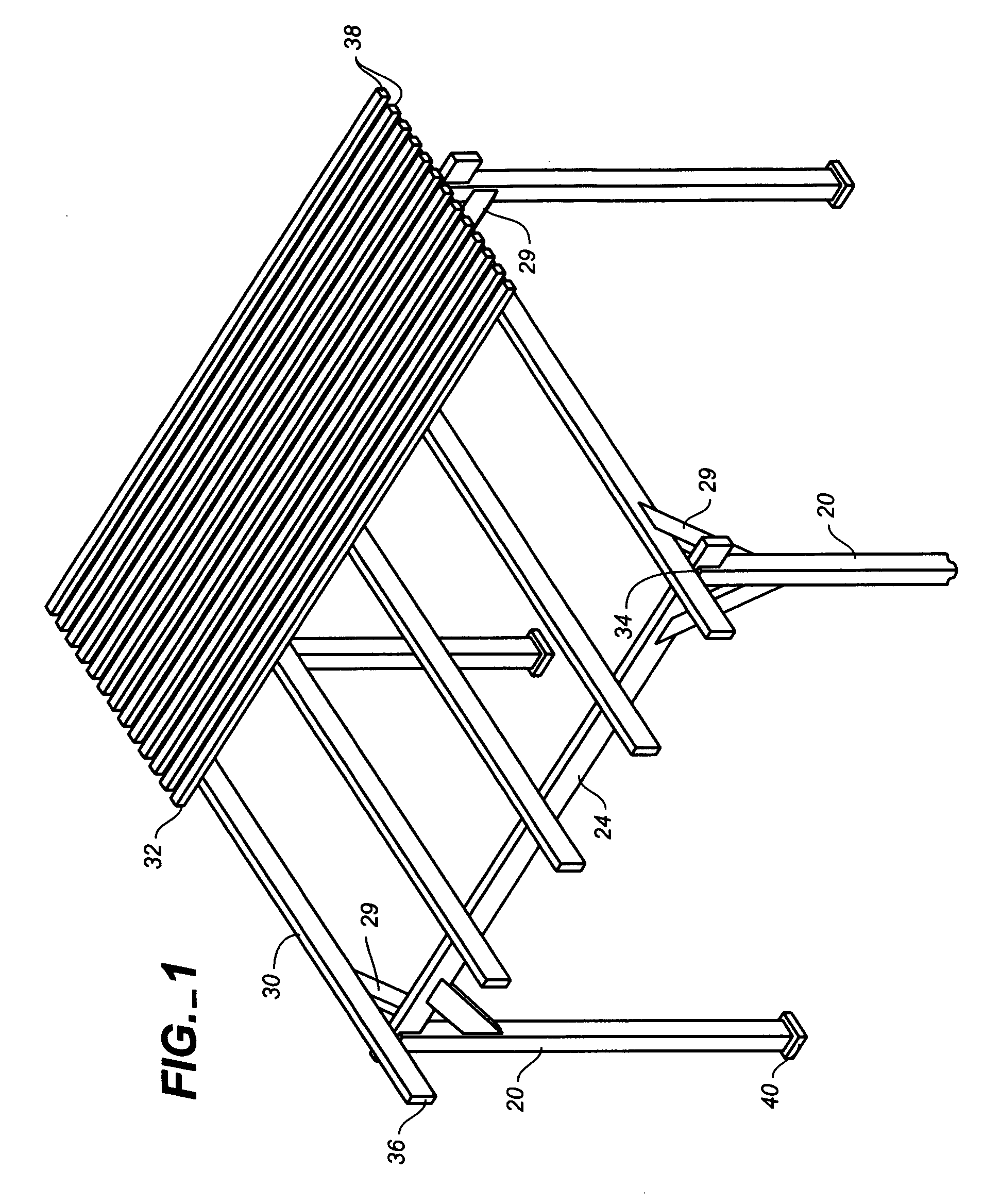
FIG. 1

[0135]The basic system provides a pergola comprising a joist, a beam, posts, and horizontal strips which are joined together systematically and with little effort using basic common tools found in most households. It can stand alone or it can be an outdoor extension of the house. Knee braces connect the beam-to-post and post-to-joist in order to stiffen the system for horizontal stability.

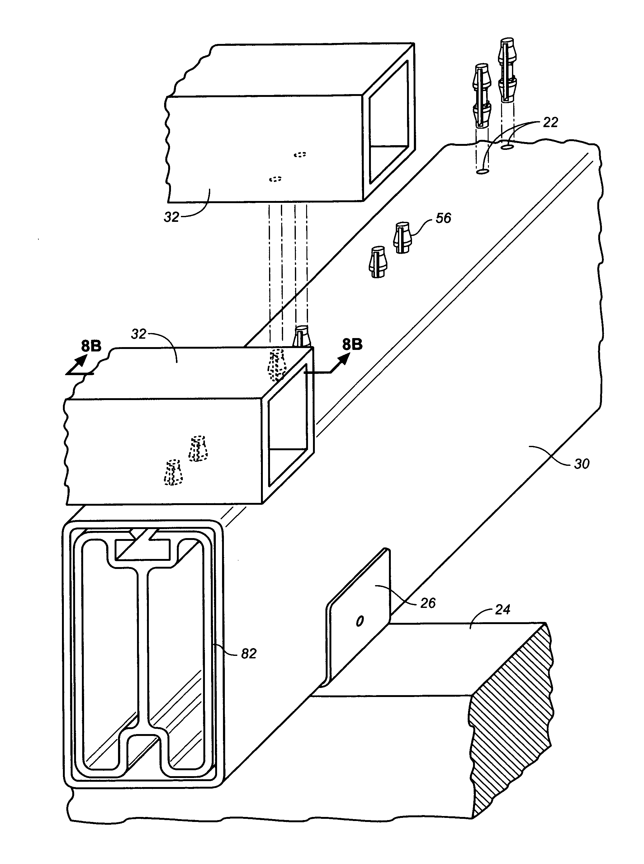
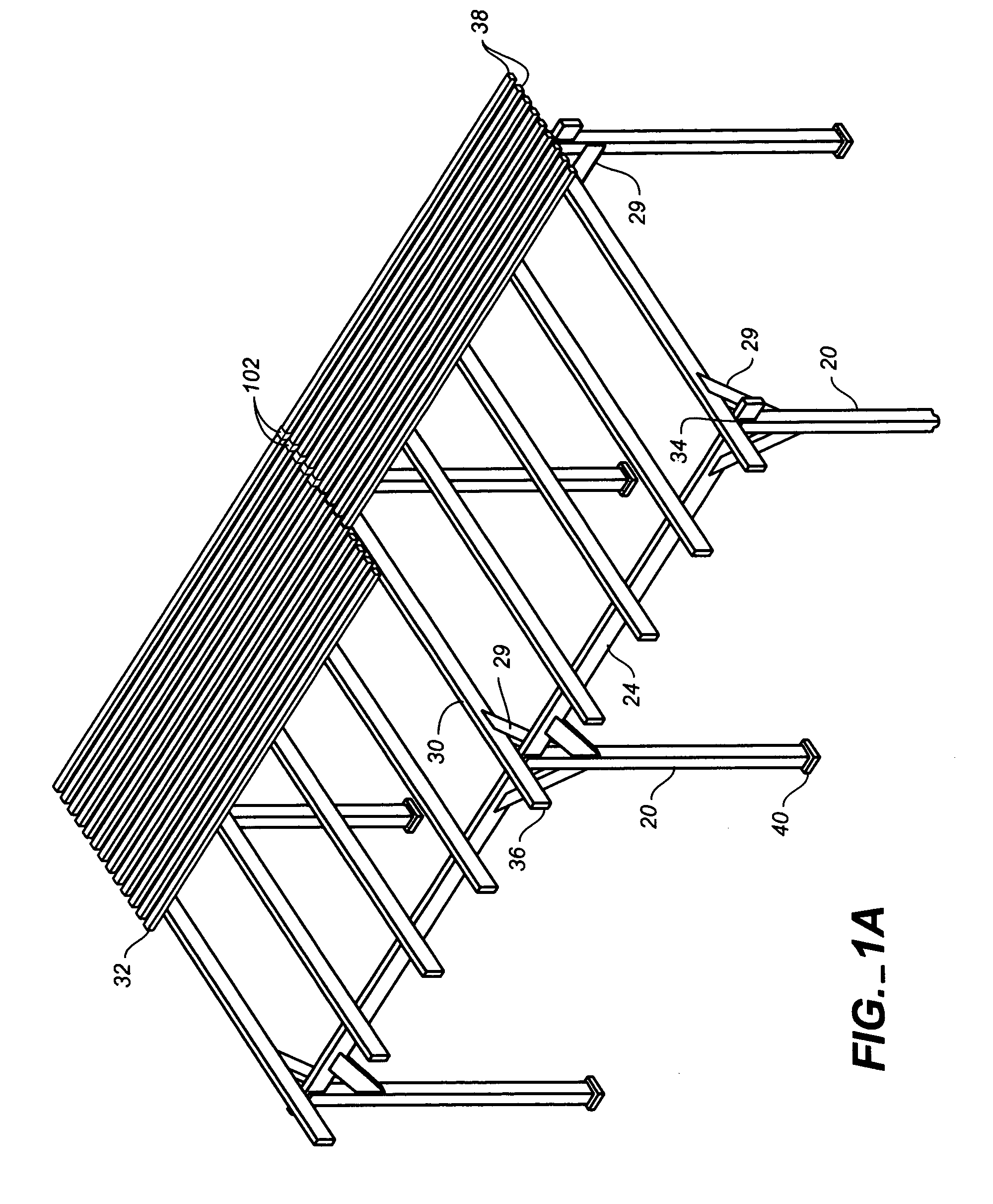
[0136]A preferred embodiment of a basic version of my pergola system is illustrated in FIG. 1 (perspective view). Four posts 20 are mounted or sleeved over wood posts or post mounts (not shown but known). The system has beams 24, joists 30, and posts 20, which are preferably made of hollow vinyl and house either a reinforcing beam 82 (FIG. 7) or a post mount (not shown), respectively. The top is covered by horizontal strips or laths 32 that are also hollow but do not have any reinforcement because they are not structural support members. The post mounts (not shown) can be made of steel or alu...


PUM


Abstract

A pergola system employs tap-lock pin (56) that readily attaches to a beam (82). The beam is encapsulated, preferably by vinyl extrusions, which allow horizontal strips to easily engage opposing end of the tap-lock pin (56). Clips (78) with protruding tap-locks (72) are secured to a substrate, allowing horizontal strips with ledges (96) to be engaged with the protruding tap-locks (72) to provide an easily installed pergola shade structure. A shroud (102) or coupler (62) allows expansion so that a plurality of pergola kits can be assembled together and so that a homeowner or do-it-yourselfer can install, alter, or retrofit the pergola(s) with minimal effort and direction.

Description

CROSS-REFERENCE TO RELATED APPLICATIONS[0001]This patent is based upon an application that claims priority of Provisional Patent Application Ser. No. 60 / 564,108, Filed Apr. 22, 2004.BACKGROUND[0002]1. Field[0003]This application relates to building structures, specifically to an easily installed user-friendly assembly system which combines substructures or substrates and building components to form a shade or activity structure.[0004]2. Prior Art[0005]Usually an outdoor shade or activity structure is constructed of horizontal and vertical wood members which are fastened together with nails or bolts and nuts. Common names of these structures are pergolas, arbors, trellises, gazebos, overheads, lath houses, bowers, armadas, awnings, porticos, and greenhouses, as well as others. Such shade structures (hereinafter pergolas) are exposed to the environment and often need regular annual maintenance that is costly as well as a nuisance.[0006]Plastic, wood, composite, and metal materials, fo...

Claims


Application Information

Patent Timeline
Patent Type & Authority Patents(United States)
IPC IPC(8): E04H14/00
CPCE04C3/06E04C3/29E04F10/08E04C2003/0421E04C2003/043E04C2003/0465
Inventor LEINES, RICHARD
Owner LEINES RICHARD
Learn More