
Exposed pad backside pressure sensor package

a pressure sensor and pad backside technology, applied in the field of pressure sensor devices, can solve problems such as tire damage, reduced vehicle stability and/or vehicle accidents, and increased fuel consumption

Inactive Publication Date: 2011-03-08
NORTH STAR INNOVATIONS
View PDF42 Cites 28 Cited by
  • Summary
  • Abstract
  • Description
  • Claims
  • Application Information

AI Technical Summary

Benefits of technology

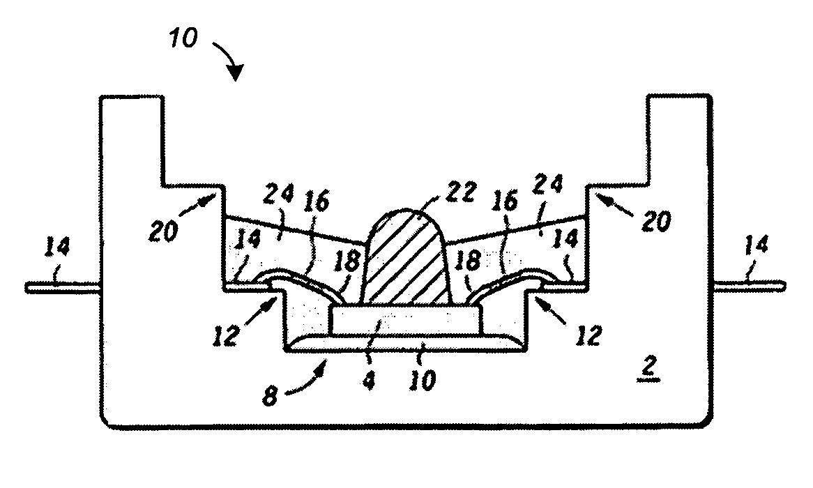
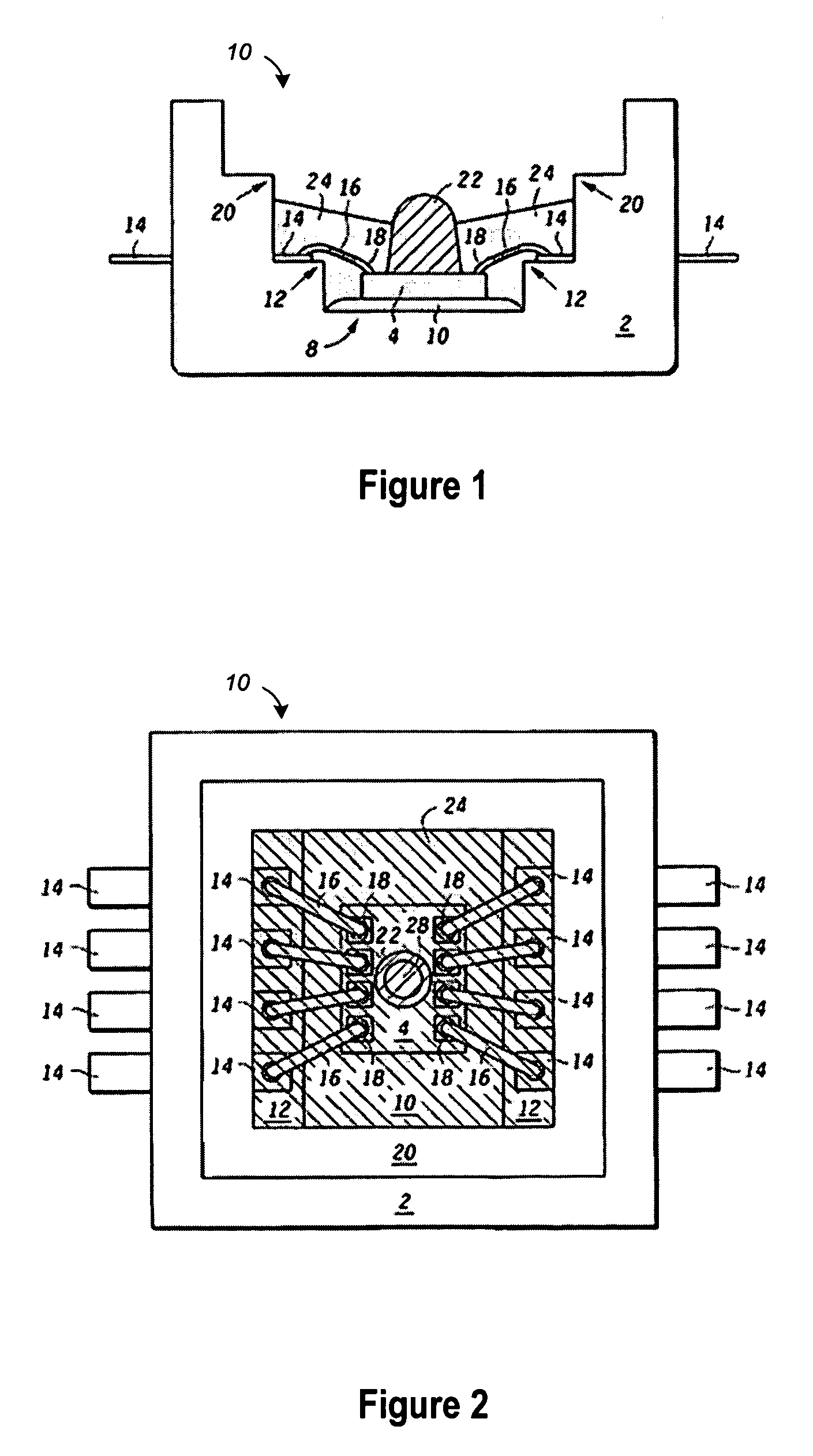
"The present invention is about improving pressure sensor devices for automotive applications. The invention provides a micro-electro mechanical system (MEMS) pressure sensor with an improved packaging scheme for producing low-cost tire pressure monitoring systems for the automotive industry. The invention solves the problem of protecting the pressure sensor from the harsh environment in the tire by adding a protective gel or coating, which adds complexity and reduces reliability. The invention uses an exposed flag and vent hole to directly expose the pressure sensor to the environment, eliminating the need for a protective film or gel. The invention also includes various methods and apparatus for fabricating and packaging the integrated silicon pressure sensor."

Problems solved by technology

Improper tire inflation can cause tire damage, increased fuel consumption, reduced vehicle stability and / or vehicle accidents if the tires blow out.
However, there are significant technical challenges to placing a pressure sensor in a tire to monitor the air pressure since the environment in the tire where the sensor is placed is quite harsh and corrosive.
To protect against the corrosive environment, internal tire pressure sensors are provided with various coatings, encapsulants, or diaphragms made from various elastic gels, polymers, or other materials, but these protection schemes add to the complexity of manufacturing such sensors, resulting in increased cost, reduced reliability, impaired centrifugal performance, and / or reduced ability to measure the air pressure (e.g., due to the presence of a thick coating on the sensing diaphragm).

Method used


Image

  • Exposed pad backside pressure sensor package
  • Exposed pad backside pressure sensor package
  • Exposed pad backside pressure sensor package

Examples


Embodiment Construction

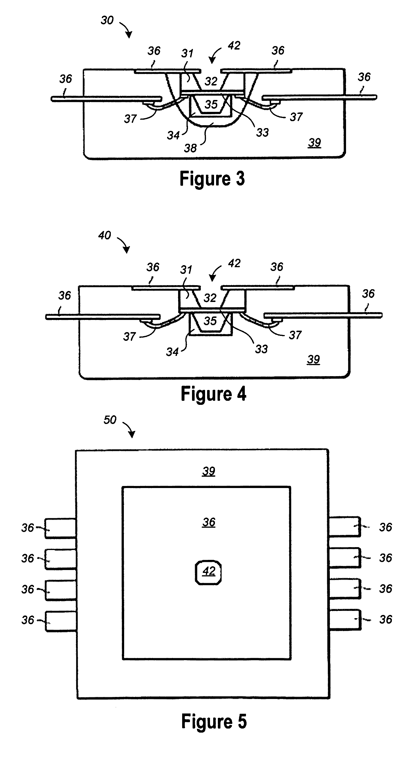
[0018]A method and apparatus are described for fabricating and packaging an integrated silicon pressure sensor having a backside piezoresistive transducer (PRT) that is directly exposed to the environment through a vent hole formed in the exposed die pad. In selected embodiments, a backside PRT die is attached to an exposed flag on a lead frame so that the pressure sensor diaphragm on the back of the PRT die is directly vented to the environment through a vent hole in the exposed flag. By virtue of forming the pressure sensor diaphragm on the monocrystalline silicon backside of the PRT die, there is no need to form a protective film or gel over the pressure sensor diaphragm since the monocrystalline silicon on the backside is a relatively robust material. In addition, the relatively sensitive circuitry (e.g., the metal lines, etc.) is on the top of the PRT die and therefore protected from the environment. The use of an exposed flag and vent hole also eliminates the need for using a ...


PUM

PropertyMeasurementUnit
corrosiveaaaaaaaaaa
pressureaaaaaaaaaa
stabilityaaaaaaaaaa

Abstract

A method and apparatus are described for fabricating an exposed backside pressure sensor (30) which protects interior electrical components (37) formed on a topside surface of a pressure sensor transducer die (31) from corrosive particles using a protective gel layer (38) and molding compound (39), but which vents a piezoresistive transducer sensor diaphragm (33) formed on a backside of the pressure sensor transducer die (31) through a vent hole (42) formed in an exposed die flag (36), enabling the sensor diaphragm (33) to directly sense pressure variations without the influence of a protective gel.

Description

BACKGROUND OF THE INVENTION[0001]1. Field of the Invention[0002]The present invention is directed in general to the field of pressure sensor devices. In one aspect, the present invention relates to a micro-electro mechanical system (MEMS) pressure sensor having an improved packaging scheme for producing low cost tire pressure monitoring systems for the automotive industry.[0003]2. Description of the Related Art[0004]Micro-Electro-Mechanical Systems (MEMS) technology is increasingly used to integrate mechanical elements, sensors, actuators, and electronics on a common silicon substrate through microfabrication technology. For example, MEMS pressure sensors can be used to automatically measure car tire pressure while the vehicle is moving so that the operators can be notified if the tires are not properly inflated. Improper tire inflation can cause tire damage, increased fuel consumption, reduced vehicle stability and / or vehicle accidents if the tires blow out. By providing real-time ...

Claims


Application Information

Patent Timeline
Patent Type & Authority Patents(United States)
IPC IPC(8): G01L7/00
CPCG01L19/0084G01L19/141H01L2924/1461H01L2924/3025H01L2924/15747H01L2224/48247H01L2224/48091H01L2224/73265H01L2224/49171H01L2224/45144H01L2924/00014H01L2924/00H01L2224/05554G01L9/08G01L17/00G01L19/06G01L19/14
Inventor HOOPER, STEPHEN R.MACDONALD, JAMES D.MCDONALD, WILLIAM G.
Owner NORTH STAR INNOVATIONS
Learn More