Gathering and stitching machine

a stitching machine and multi-part technology, applied in the direction of pile separation, article feeders, article delivery, etc., can solve the problems of reducing stitching precision, entanglement of the load, so as to achieve high quality stitching, improve the quality of stitching, and reduce the load distribution. effect of components to be moved

Inactive Publication Date: 2011-03-08
FERAG AG
View PDF17 Cites 5 Cited by
  • Summary
  • Abstract
  • Description
  • Claims
  • Application Information

AI Technical Summary

Benefits of technology

[0011]With the invention, thus one not only does away with the rigid fastening of the saddle-like rest on the conveyor member, as is usual with known stitching apparatus, but it is supplemented in a synergistic manner by the pivotably movable mounting of the stitching heads along a circular revolving path. Since the stitching heads as well as the saddle-like rests play a part in the pivoting movement, the load distribution on the components to be moved is significantly more favourable, since the pivot movement is distributed onto both device parts. Moreover, a larger degree of freedom for the design of the device and a mutual matching of the stitching head and rests results, so that the quality of the stitching may also be improved.
[0012]This movable mounting is designed in a manner such that the rest edges of the saddle-like rest and the fronts of the stitching head (“stitching head tips”) may be led at a lower, greater or equal speed in comparison to the conveyor member speed, in the whole stitching region, wherein the optimal alignment of the stitching heads and the rests in the stitching plane is always ensured. Solutions with which the speed of the rests in the stitching region is the same or larger than the conveyor member speed are particularly advantageous for a high quality stitching in cooperation with rotation stitching apparatus.

Problems solved by technology

Moreover, the lifting of the printed sheets from the saddle, which is envisaged there, is laborious and is disadvantageous with regard to the precision on the stitching.
With the conveyor speeds which are common today in the medium performance or high performance field, such a speed reduction and subsequent acceleration entails enormous loading of the participating components.
A pivoting of the rests between the conveyor chains of the pull means in the stitching region is no longer possible.

Method used


Image

  • Gathering and stitching machine
  • Gathering and stitching machine
  • Gathering and stitching machine

Examples


Embodiment Construction

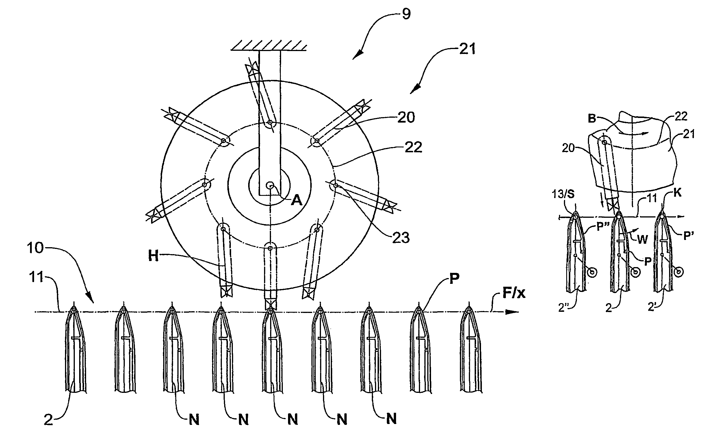
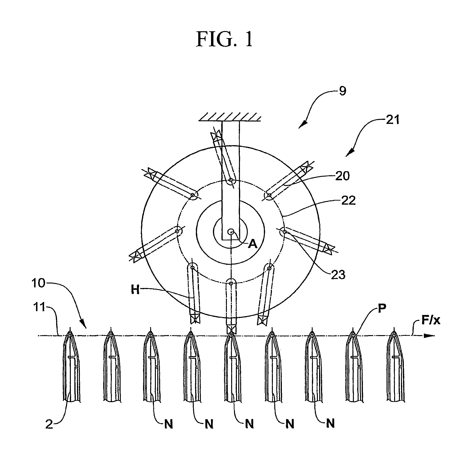
[0022]A cut-out of the collecting and stitching device is shown in the region of a stitching head wheel 21 in a schematic view from the side in FIG. 1, with which eight stitching heads 20 rotating on the stitching head wheel 21 revolve about the axis A. The device and the method according to FIG. 1 do not correspond to the present invention, since essential features of the invention are absent. In the comparative example of FIG. 1, the stitching heads 20 and the stitching head wheel 21 are represented in a very schematic manner, and a wire section dispensing unit is left out completely. Only a cut-out of a ladder circulation conveyor (Leiterumlauf), also called circulating collection conveyor 10, is shown. The circulating collection conveyor 10 comprises a multitude of saddle-like rests 2, which are led past different processing stations along a main conveying direction F by a conveyor member 11, wherein only one such processing station in the form of the stitching station is shown ...


PUM


Abstract

A new gathering and stitching machine (10) and a new method for operating a gathering and stitching machine (1) are proposed, which make it possible to drive in the staples (K) in a positionally correct manner and to close them satisfactorily even in the case of relatively short staple setting times. This is achieved by the novel control of the position of the staple heads (20) and the saddle-shaped supports (2, 30, 40, 50) in the region of the interaction during stapling. It is an essential feature of the present invention that the staple head (20) and the support (2, 30, 40, 50) are pivoted towards one another in such a way that they come to lie within a common stapling plane (H). This means that the saddle plane which is defined by the pivoting axis (S) of the saddle-shaped support (2, 30, 40, 50) and the support edge (13) and the staple-head plane which is defined by the pivoting axis of the staple head (20) and the ram tip are superimposed on one another in the region of the interaction and for the duration of the interaction and define what is known as the stapling plane (H). Here, the stapling plane (H) is pivoted continuously, with the result that it stands orthogonally on the main conveying plane (X) only in a central position.

Description

FIELD OF THE INVENTION[0001]The invention lies in the field of collecting and processing multi-part folded printed products and relates to a device and a method for the collection, transport, possible processing and the stitching of printed products.DESCRIPTION OF RELATED ART[0002]Collecting and stitching devices with endlessly revolving conveyor members, which comprise a plurality of rests, are known from the state of the art. Basically, collecting and stitching devices serve for the manufacture of magazines, newspapers, brochures etc., from finished printed and folded sheets. For this, the printed sheets and the cover are applied over one another, aligned and stitched, in the desired sequence.[0003]A device for processing folded printed sheets is known from EP0202507, with which a plurality of saddle-like rests are provided for the straddled receipt of the printed sheets along a conveyor path, with a rest edge aligned transversely to the conveyor path. The endlessly revolving conv...

Claims


Application Information

Patent Timeline
Patent Type & Authority Patents(United States)
IPC IPC(8): B42B5/00B65H39/00B65H41/00B65H5/30B42B2/02B42B2/00
CPCB42B4/02
Inventor RAMSEIER, MARCEL
Owner FERAG AG
Why Eureka
Try Eureka