
Dimmable LED lamp

a technology of led lamps and diodes, applied in the direction of electric variable regulation, process and machine control, instruments, etc., can solve the problems of inherently inefficient converters, prolonging life, and limitation of ac-powered leds, so as to prolong the life of led lamps, reduce flicker, and increase light output

Inactive Publication Date: 2011-03-08
NEXT GEN ILLUMINATION
View PDF56 Cites 26 Cited by
  • Summary
  • Abstract
  • Description
  • Claims
  • Application Information

AI Technical Summary

Benefits of technology

The solution extends the life expectancy of LED lamps by reducing junction temperature and achieving nearly double the life at half the illumination output, while maintaining compatibility with standard dimming devices and reducing heat and power consumption.

Problems solved by technology

Thus, it is known in the art that dimming a lamp results in prolonged life.
For years, this property led to a limitation on AC-powered LEDs in which an AC-DC converter was required as part of the LED lamp.
Such a converter is inherently inefficient, as it serves as an additional source of heat and requires space not available in many lamp applications.
The '259 patent thus provides an LED lamp that runs on AC power without the necessity of an AC-DC converter; however, the LED lamp disclosed in the '259 patent is not capable of being dimmed without flickering due to the inherent instability of AC current.
That is, in virtually all applications, it is well known that AC power supplied by the public grid will fluctuate in both voltage and frequency, yet the '259 patent does not account for such fluctuations.
While rheostats are well suited to dimming an incandescent bulb, rheostats are not as efficient as some would believe because rheostats do not actually reduce the power used by the circuit; rather, the power is converted to heat by the rheostat.
However, no prior art solves the problem of flickering when using a rheostat with an AC-powered LED lamp.
When a rheostat is connected to an LED lamp, the square wave defined by the on voltage creates an unwanted visible flicker.
When these types of semiconducting dimmers are used to dim an AC-powered LED lamp, the phase-controlled sinusoidal voltage waveform nonetheless results in a visible flicker and other unwanted harmonics.

Method used


Image

  • Dimmable LED lamp
  • Dimmable LED lamp
  • Dimmable LED lamp

Examples


Embodiment Construction

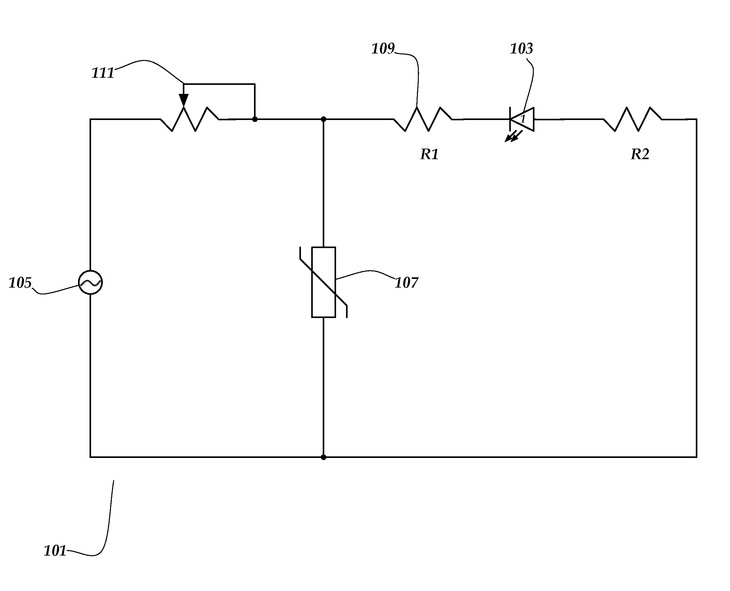
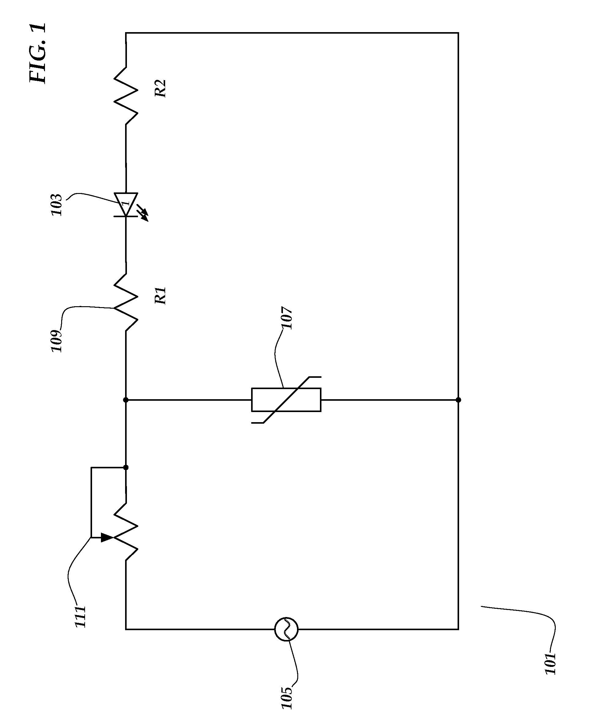
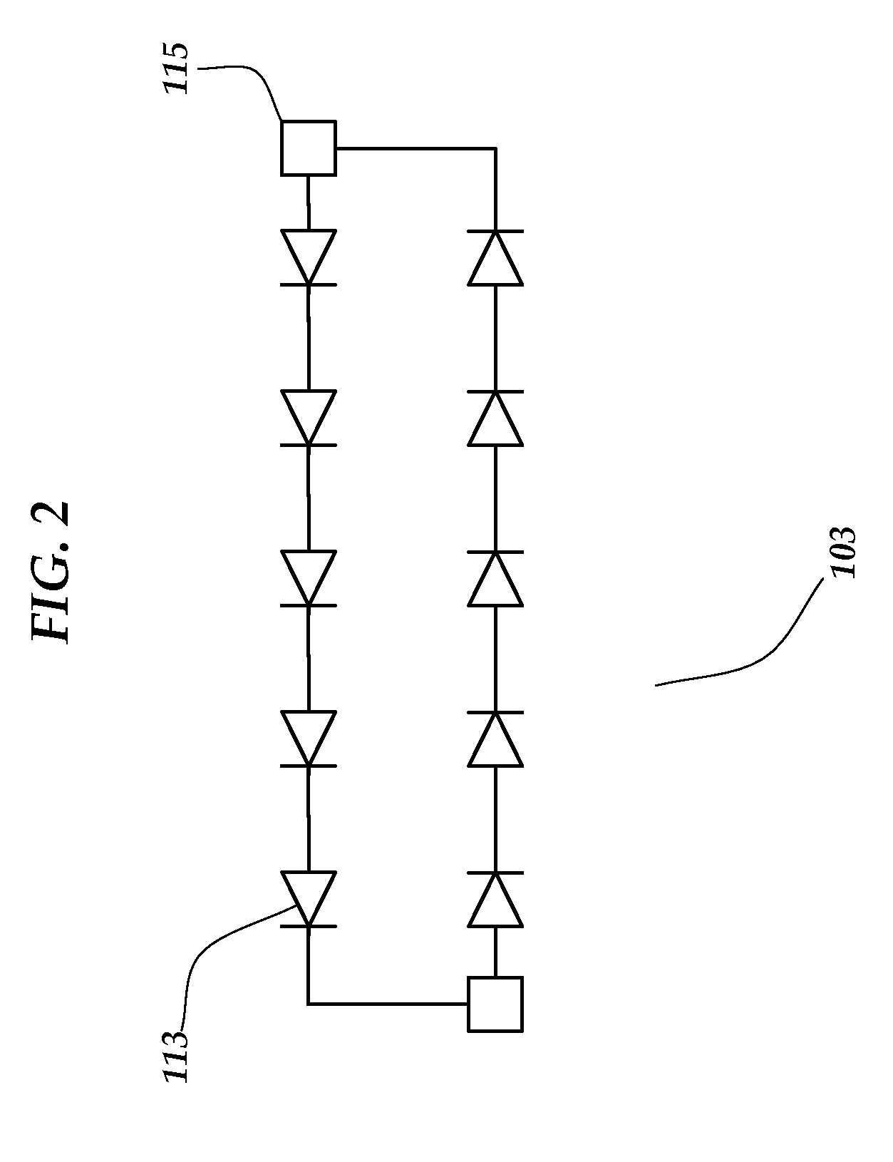
[0041]The invention as disclosed herein provides a virtually flicker-free, AC-powered LED lamp capable of being preferentially dimmed. As seen in FIG. 1, AC-powered LED lamp 101 comprises a circuit in which one or more bi-directional LED chips 103 are connected to AC power source 105. Bi-directional LED chip 103 is a typical AC-powered LED binary chip designed to be either switched off or supplied with full power from a power grid, such as 110V AC or 220V AC. One bi-directional LED chip is manufactured by Seoul Semiconductor under the trade name Acriche. A varistor 107 is placed in parallel to bi-directional LED chip 103 in order to shunt excess current due to voltage spikes from AC power source 105. Resistors 109 having substantially equivalent resistance are connected to either side of each bi-directional LED chip 103 in order to apply the proper predetermined amount of voltage across each bi-directional LED chip 103. A rheostat 111 may be added in series with AC power source 105 ...


PUM


Abstract

An LED lamp utilizes AC power and bi-directional LED chips to provide dimming capabilities. The dimming capabilities of the lamp reduce the junction temperature of the LEDs on the bi-directional LED chips and thus prolong the life expectancy of the LED lamp.

Description

GOVERNMENTAL RIGHTS[0001]None.CROSS REFERENCES[0002]None.BACKGROUND OF THE INVENTION[0003]The invention relates to the field of light-emitting diode (“LED”) lamps, specifically LED lamps capable of being dimmed to reduce energy usage and prolong the life of the lamp.[0004]Lamps of all kinds, whether incandescent, halogen, sodium vapor, or LED, produce heat as a byproduct of the electrical production of light. The hotter the lamp temperature becomes the shorter the life of the lamp. Lamps are typically designed to provide a designed life at a specified voltage and amperage. For instance, a typical incandescent bulb powered with 110 volts of AC power that draws 25 to 110 W has a typical life expectancy of 2,000 hours. If the voltage applied to an incandescent lamp's filament is reduced by 5%, the life of the bulb is doubled and the light output is reduced by approximately 20%. Thus, it is known in the art that dimming a lamp results in prolonged life.[0005]Energy prices have generally...

Claims


Application Information

Patent Timeline
Patent Type & Authority Patents(United States)
IPC IPC(8): G05F1/00
CPCH05B33/0809H05B33/0815Y10S315/04H05B45/31H05B45/30H05B45/59
Inventor ANG, SIMON SAW-TEONGBEAVER, JEFFREY ALAN
Owner NEXT GEN ILLUMINATION
Learn More