Method of producing a heat exchanger module

a heat exchanger and module technology, applied in the direction of tubular elements, stationary tubular conduit assemblies, tubular elements, etc., can solve the problem of not providing perfect thermal insulation, and achieve the effect of eliminating the thermal bridg

Inactive Publication Date: 2011-03-15
VALEO SYST THERMIQUES
View PDF10 Cites 4 Cited by
  • Summary
  • Abstract
  • Description
  • Claims
  • Application Information

AI Technical Summary

Benefits of technology

[0008]The precise object of the invention is a heat-exchange fin which remedies these disadvantages by mak

Problems solved by technology

These various means, although they reduce exchanges of heat, do not, however, provide pe

Method used


Image

  • Method of producing a heat exchanger module
  • Method of producing a heat exchanger module
  • Method of producing a heat exchanger module

Examples


Embodiment Construction

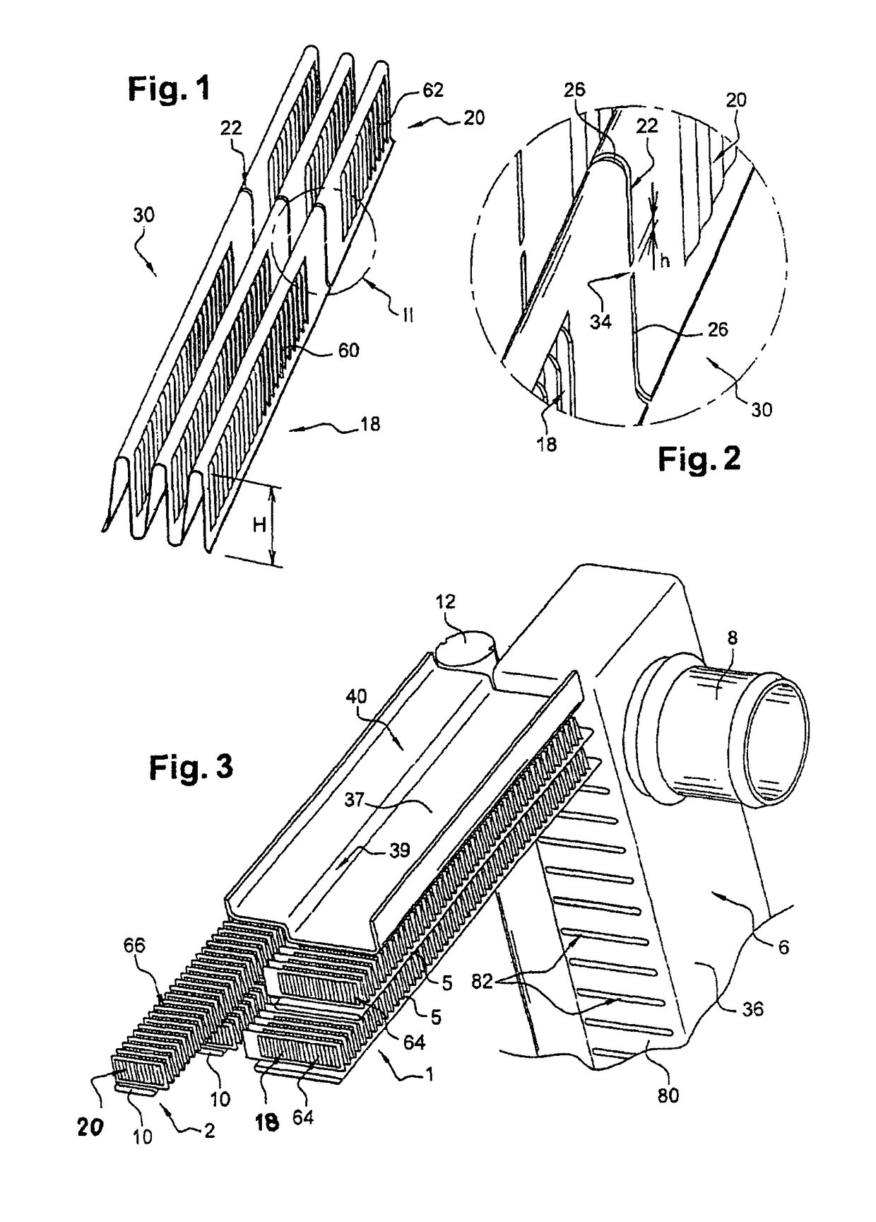
[0047]FIGS. 1 and 2 depict a heat-exchange fin, particularly for cooling, according to the invention. Said fin consists of a strip 30 comprising a first heat-exchange zone 18, intended to collaborate with tubes of a first heat exchanger, and a second heat-exchange zone 20, intended to collaborate with tubes of a second heat exchanger. Such fins are able to perform an exchange of heat between the air and a fluid circulating through the tubes. They are, for example, made of aluminum.

[0048]Each heat-exchange zone 18, 20 may be equipped with means for disturbing the flow of air, also known as louvers 60, 62, known to those skilled in the art.

[0049]Advantageously, the configuration of said louvers is adapted to suit the type of exchanger equipped. They may, for example, be orientated top-to-tail on either side of an axis of symmetry, this being in each heat-exchange zone 18, 20. In other words, in the first heat-exchange zone 18 there are, on each side of a first axis of symmetry, louver...


PUM

PropertyMeasurementUnit
Fractionaaaaaaaaaa
Shapeaaaaaaaaaa
Heightaaaaaaaaaa

Abstract

The invention relates to a heat exchange fin, particularly for cooling, consisting of a strip (30) comprising a first heat-exchange zone (18), intended to collaborate with tubes of a first heat exchanger, and a second heat-exchange zone (20), intended to collaborate with tubes of a second heat exchanger.
According to the invention, said strip comprises a zone of weakness (22) able to allow it to be parted into a first element (64) comprising said first heat-exchange zone (18) and a second element (66) comprising said second heat-exchange zone (20).
The invention also relates to a heat-exchange module comprising such a fin and to a method of producing such a module.

Description

BACKGROUND OF THE INVENTION[0001]1. Field of the Invention[0002]The invention relates to a heat-exchange fin, particularly for cooling, to a heat-exchange module comprising such a fin and to a method of producing such a module. It finds its applications in the field of motor vehicles in particular.[0003]It relates more particularly to a heat-exchange fin, particularly for cooling, consisting of a strip comprising a first heat-exchange zone, intended to collaborate with tubes of a first heat exchanger, and a second heat-exchange zone, intended to collaborate with tubes of a second heat exchanger.[0004]2. Description of the Related Art[0005]It is known practice for such fins to be used in heat-exchange modules, also known as multi-exchangers, comprising at least a first and a second exchanger having at least one common component, each exchanger comprising fluid-circulation tubes, generally flat and uniformly spaced, with which each of the heat-exchange zones of the fins collaborates.[...

Claims


Application Information

Patent Timeline
IPC IPC(8): F28F13/00F28D1/00B21D53/06B21D53/08F28D1/04F28F1/12F28F9/00
CPCB21D53/085F28D1/0435F28F1/128F28F9/001F28D2021/0084Y10T29/4935F28D2021/0094
Inventor RIONDET, CHRISTIANTRAVERS, FLORENTARNESEN, JENS-PETTERLESUEUR, JEAN-MARCBAUERHEIM, ALAINSANCHIS, ALEXANDRE
Owner VALEO SYST THERMIQUES
Why Eureka
Try Eureka