
Suspension protection systems and methods

a suspension protection and suspension technology, applied in the direction of shock absorbers, steering devices, cycle equipment, etc., can solve the problems of overcompression of the suspension system, damage to the suspension system, and the suspension system becomes overcompressed, so as to prevent unwanted damage to the fork of the motorcycle, reduce the effect of compressive load, and easy and efficient installation

Inactive Publication Date: 2013-03-12
MARTIN JEFFERY
View PDF16 Cites 0 Cited by
  • Summary
  • Abstract
  • Description
  • Claims
  • Application Information

AI Technical Summary

Benefits of technology

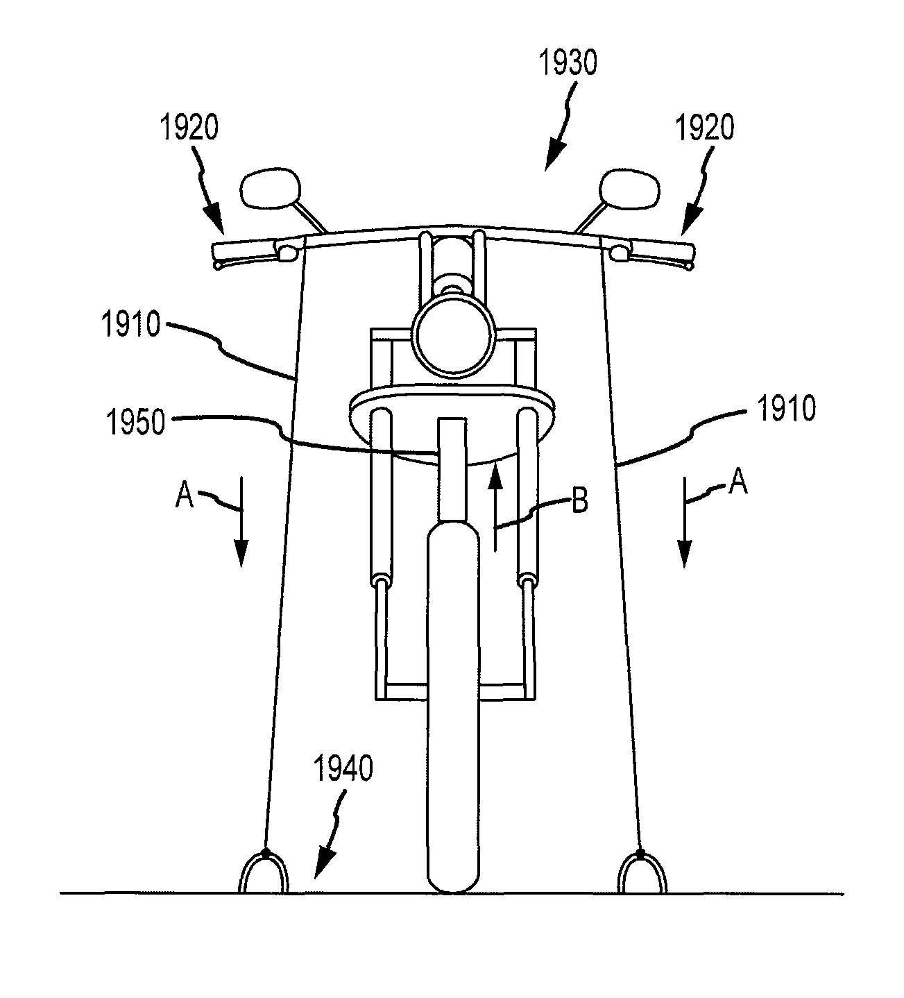
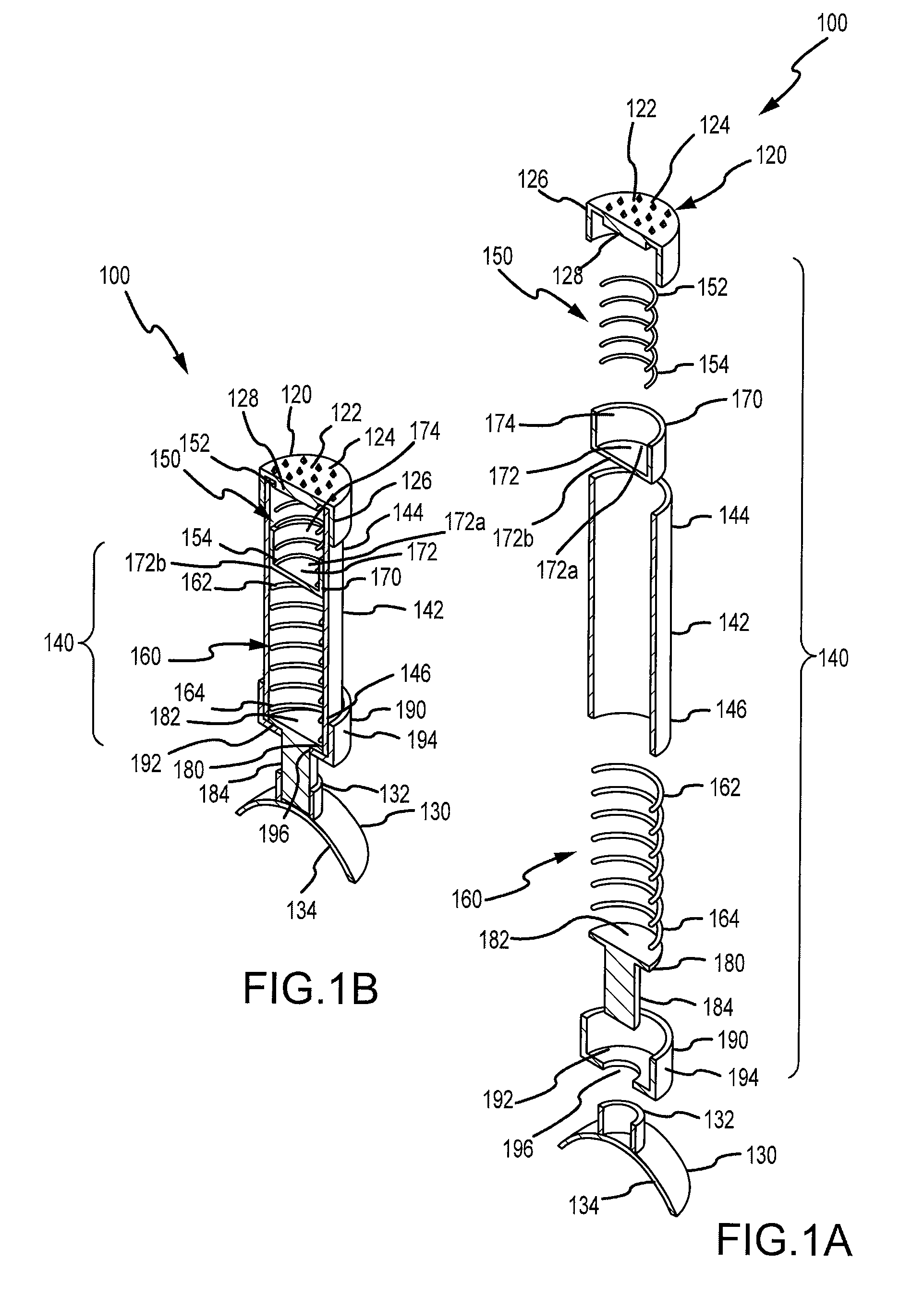
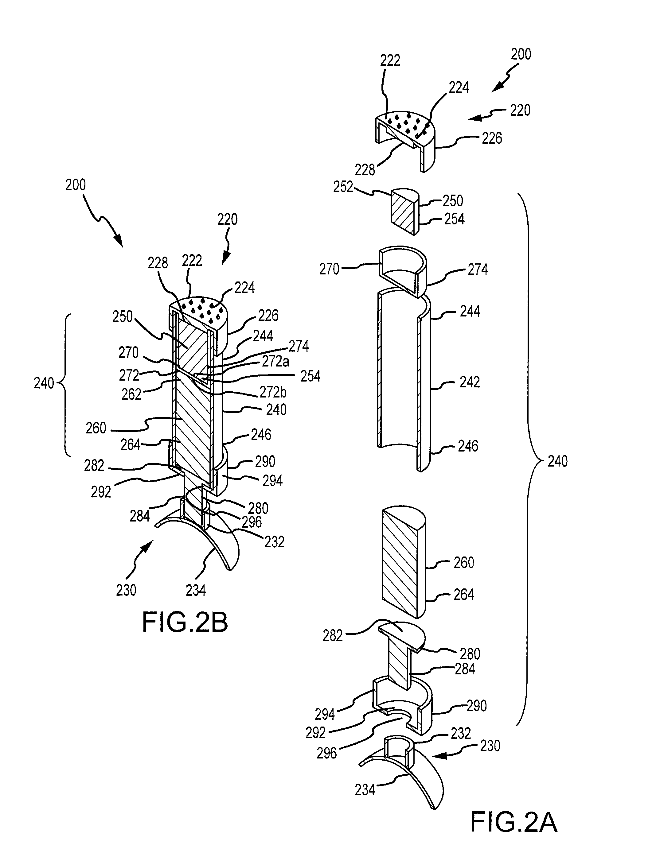
[0004]Embodiments disclosed herein provide devices and methods for protecting the suspension of a transported vehicle. Such devices can absorb or reduce a compressive load that is transferred to the vehicle suspension when the vehicle is strapped down or otherwise restrained to a trailer, a truck bed, or other transport surface. In some cases, a protection device can be placed between the fender and the tire of a motorcycle, so as to prevent unwanted damage from occurring to the motorcycle fork. Such devices can protect springs in the motorcycle fork from becoming overcompressed during transport, which may otherwise occur if the device is not used. Advantageously, embodiments of the present invention provide suspension protection systems that can be easily and efficiently installed by a user or operator onto a vehicle such as a motorcycle. Such suspension protection systems can exhibit a variable compressibility profile. Moreover, embodiments of the present invention encompass suspension protection systems that provide positive benefits of dynamic opposing forces, for example by increasing or modulating dynamic opposing forces on restraining or tie-down straps which secure the vehicle. During transport, as a vehicle is subject to compressive forces such as travel over bumpy roads, braking, and cornering events, the suspension protection system can prevent the suspension of the vehicle from becoming subject to unwanted levels of compression, and can also maintain tautness in cinching devices used to secure the vehicle to a transport surface.
[0007]In a further aspect, embodiments of the present invention encompass a method of installing a suspension protection system in a vehicle. The method may include compressing the suspension protection system with a first compressive force so as to shorten the suspension protection system, placing the suspension protection system between a suspension mount of the vehicle and a tire of the vehicle, allowing the system to lengthen such that a suspension mount engagement of the suspension protection system contacts the suspension mount and a tire engagement member of the suspension protection system contacts the tire, and fastening the vehicle relative to a surface so as to compress the suspension protection system with a second compressive force that is greater than the first compressive force. In some cases, a first friction force opposes relative movement between the suspension mount engagement member of the suspension protection system and the suspension mount, and a second friction force opposes relative movement between the tire engagement member of the suspension protection system and the tire.

Problems solved by technology

However, often the suspension system of the vehicle becomes overcompressed during loading, or during transport as the trailer or truck travels over bumpy roads.
Overcompression in the suspension system can also occur as a result of braking and cornering events during transport.
Unfortunately, overcompression can be damaging to a suspension system, particularly when overcompression occurs frequently or over extended periods of time.
For example, damping mechanisms and other components of suspension systems may suffer from air or fluid loss, spring fatigue, seal damage, and the like.
Current approaches for protecting suspension systems often involve devices which are difficult to install in a motorcycle or other transported vehicle, or are static and lack the benefit of dynamic opposing forces.

Method used


Image

  • Suspension protection systems and methods
  • Suspension protection systems and methods
  • Suspension protection systems and methods

Examples


Embodiment Construction

[0029]Embodiments of the present invention can be adapted for use with any of a variety of vehicles, including motorcycles, all terrain vehicles, quad cycles, three wheelers, and the like. These systems and methods embodiment are well suited for use with any vehicle having a suspension that may become overcompressed during loading or transport.

[0030]Typically, embodiments include a rebounding device or assembly having a desired compressibility profile. The term “compressibility” can refer to the amount or magnitude of change in the length or other dimension or property of a compressible device in response to an applied stress, pressure, or force. As noted above, compressible devices can include rebounding members such as springs, elastomers, elasticized members, and the like. Such a suspension protection systems can exhibit a variable compressibility profile. For example, a suspension protection system can provide a compressibility profile that encompasses a first higher compressibi...


PUM


Abstract

Suspension protection devices and methods involve a suspension mount engagement member configured to contact a suspension mount of a vehicle, a tire engagement member configured to contact a tire of the vehicle, and a rebounding assembly coupled between the suspension mount engagement member and the tire engagement member. The rebounding assembly can include a support, a first rebounding member, and a second rebounding member, wherein the first rebounding member is more compressible than the second rebounding member.

Description

BACKGROUND OF THE INVENTION[0001]Embodiments of the present invention relate to systems and methods for protecting the suspension of a vehicle, and more particularly to rebounding mechanisms for protecting the fork suspension of a motorcycle.[0002]When trailering or carrying a motorcycle or any other type of vehicle, it is common to load the vehicle onto a trailer, a bed of a truck, or any other surface. The vehicle is then tightly strapped down to the trailer or truck bed. Accordingly, the suspension system of the vehicle absorbs a compressive load that results from strapping down the vehicle. Some degree of induced compression in the suspension system is desirable, and can help provide stability and prevent or inhibit the vehicle from tipping over. However, often the suspension system of the vehicle becomes overcompressed during loading, or during transport as the trailer or truck travels over bumpy roads. Overcompression in the suspension system can also occur as a result of brak...

Claims


Application Information

Patent Timeline
Patent Type & Authority Patents(United States)
IPC IPC(8): F16D57/00B62K1/00
CPCF16F3/023F16F3/093
Inventor MARTIN, JEFFERY
Owner MARTIN JEFFERY
Learn More