Eureka AIR delivers breakthrough ideas for toughest innovation challenges, trusted by R&D personnel around the world.

Disposal of slurry in underground geologic formations

a geologic formation and underground technology, applied in the direction of biological sludge treatment, transportation and packaging, borehole/well accessories, etc., can solve the problems of large amount of fuel, high negative heat value, and serious disposal problem of sewage and wastewater treatment plant sludg

Inactive Publication Date: 2011-03-15
SGC ADVISORS
View PDF51 Cites 8 Cited by
  • Summary
  • Abstract
  • Description
  • Claims
  • Application Information

AI Technical Summary

Problems solved by technology

Sludge from sewage and wastewater treatment plants represents a serious disposal problem.
Incineration, however, requires large amounts of fuel because sewage sludge contains a high volume of water, giving it a highly negative heat value.
Moreover, use as daily cover in a landfill or fertilizer has disadvantages because sludge generates undesirable odors and can lead to contamination of soil or landfill from, for example, heavy metals or pathogens.
As the foregoing demonstrates, the disposal of sewage has become increasingly expensive and difficult while at the same time there is a growing need for renewable energy and green power.

Method used

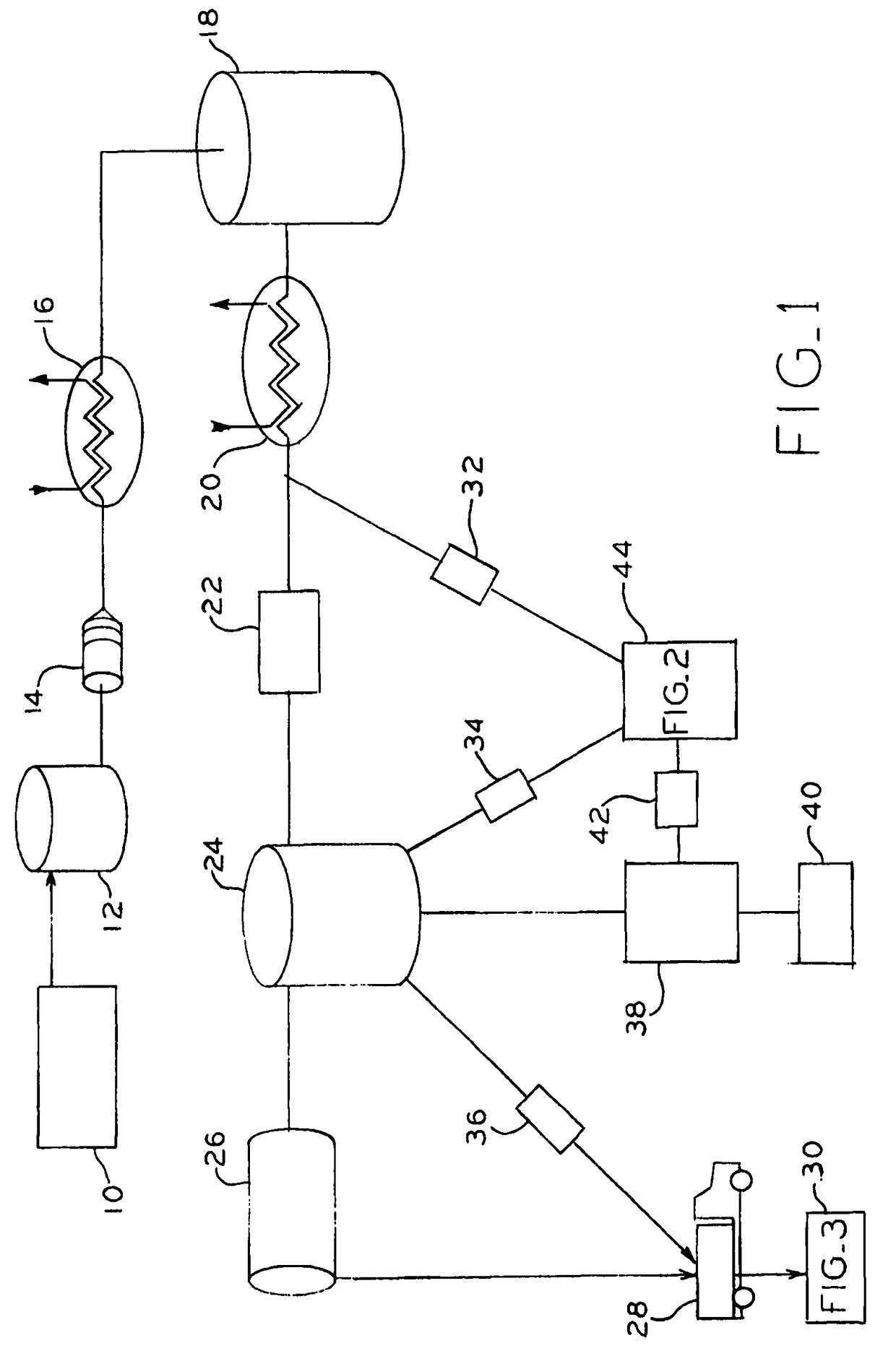
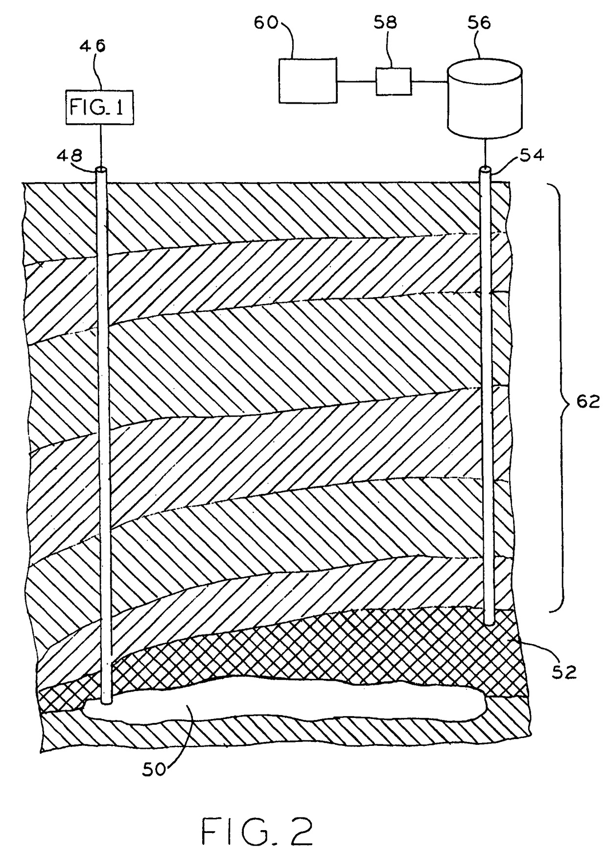
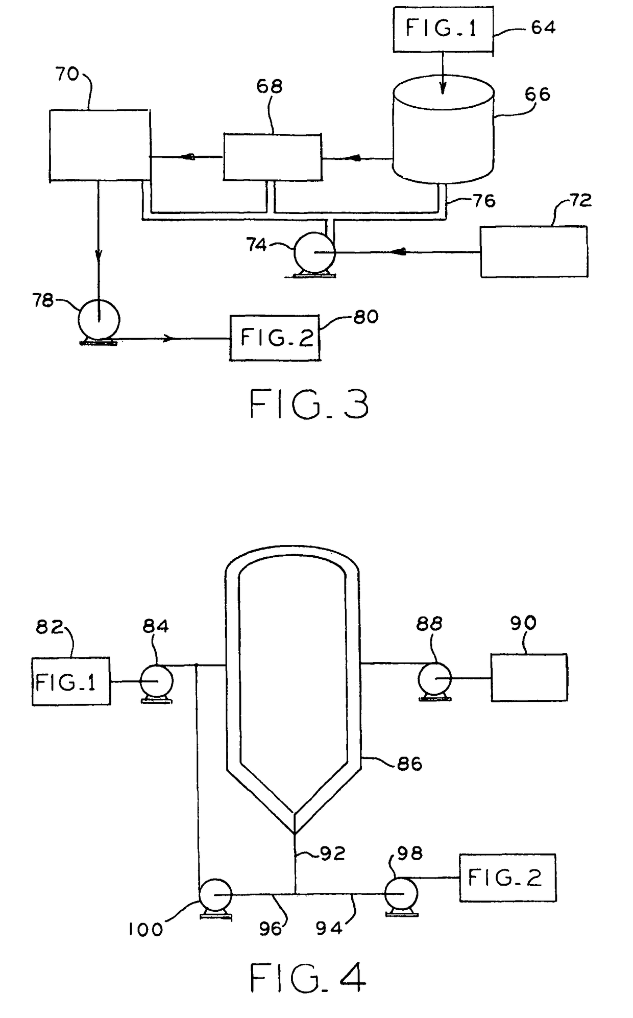

Image

  • Disposal of slurry in underground geologic formations
  • Disposal of slurry in underground geologic formations
  • Disposal of slurry in underground geologic formations

Examples


example 1

[0055]Sewage sludge was subjected to slurry treatment as described in the current invention. The following table indicates viscosity of the resulting slurry at 177° F. and at variable shear rates:

[0056]

Shear RateViscosity(sec−1)(cP)1.5310733.066445.1144210.2126551.0781102.1249153.2136170.2333306.4122340.4620510.69151021.389

example 2

[0057]Sewage sludge from a wastewater treatment plant is received in a receiving tank. Sewage sludge is treated in order to adjust the particle size and viscosity by mixing and optionally, addition of water, to produce unreacted slurry. The slurry is then preheated through heat exchangers at a temperature of about 150° C. to 315° C. under pressure of about 400 psi to 1200 psi which is sufficient to keep the water present in the slurry in liquid state.

[0058]Preheated slurry is then held at a temperature of about 150° C. to 315° C. under pressure of about 400 psi to 1200 psi in the reactor, which causes rupturing of biological cells and release of the water trapped in the cells. The slurry is then subjected to a pressure let-down which causes carbon dioxide to released from the slurry as a gas. The carbon dioxide is collected.

[0059]The slurry is cooled to a temperature of about 35-60° C. and is inoculated with the microbial inoculum. Upon mixing with the microbial inoculum, the slurry...

example 3

[0061]Sewage sludge was subjected to slurry treatment as described herein. The following table shows the distribution of the particle size in the resulting slurry:

[0062]

SlurryPercent ofparticle sizeslurry under the(micrometers)particle size149967483537644712537682560205515491040522310


PUM


Abstract

The current invention provides processes and apparatuses for introducing slurry into underground geological formations thereby disposing of the slurry, while also sequestering carbon dioxide and collecting methane from the slurry.

Description

CROSS-REFERENCE TO RELATED APPLICATION[0001]This application is related to and claims the benefit under 35 U.S.C. §365 of International Application No. PCT / US2008 / 061529, filed Apr. 25, 2008, which claims the benefit under 35 U.S.C. §119 of U.S. Provisional Application No. 60 / 926,709, filed Apr. 27, 2007, the disclosures of which are expressly incorporated herein by reference.FIELD OF THE INVENTION[0002]The current invention provides processes and apparatuses for introducing slurry into underground geological formations thereby beneficially using the slurry to increase methane gas recovery, while also sequestering carbon dioxide from the slurry.BACKGROUND OF THE INVENTION[0003]Sludge from sewage and wastewater treatment plants represents a serious disposal problem. Currently, sewage sludge is incinerated, disposed of in or used as alternative daily cover in landfills and used as fertilizer. Incineration, however, requires large amounts of fuel because sewage sludge contains a high v...

Claims


Application Information

Patent Timeline
Patent Type & Authority Patents(United States)
IPC IPC(8): B65G5/00
CPCB09B1/008C12M21/04C12M23/18C12M35/08C12P5/023E21B41/0057C02F11/04Y02C10/14Y02E50/343Y02C20/40Y02E50/30Y02W10/20
Inventor KEARNEY, RAYMOND J.
Owner SGC ADVISORS
Why Eureka
Eureka Blog
Learn More