Dialysis system having integrated pneumatic manifold

Active Publication Date: 2011-03-15
BAXTER HEALTHCARE SA +1
View PDF109 Cites 60 Cited by
  • Summary
  • Abstract
  • Description
  • Claims
  • Application Information

AI Technical Summary

Benefits of technology

The present disclosure relates to an integrated pneumatic manifold with direct mounted or encapsulated parts that eliminate the need for certain tubes or hoses. The manifold can be used in medical fluid delivery treatments, such as any type of dialysis t

Problems solved by technology

For example, tubing does not have to be detached from barbed ports fittings, which

Method used


Image

  • Dialysis system having integrated pneumatic manifold
  • Dialysis system having integrated pneumatic manifold
  • Dialysis system having integrated pneumatic manifold

Examples


Embodiment Construction

Pneumatic Hardware Configurations

Referring now to the drawings and in particular to FIGS. 4 to 8, pressure manifold assembly 100 illustrates one embodiment of the present disclosure. Assembly 100 includes a top plate 102, a bottom valve plate 104 and a gasket 106 sandwiched between top plate 102 and bottom valve plate 104. Top plate 102 can be made of aluminum or other lightweight material that can be threaded or fitted with threaded inserts.

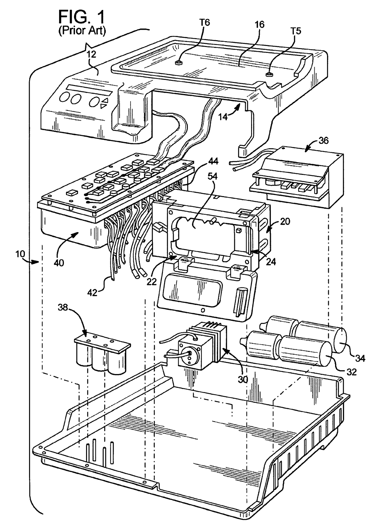
Manifold assembly 100 includes a first header 108, which is attached to manifold top plate 102 in a sealed manner using o-ring seals 110 and screws 112. O-Ring seals 110 provide a leak tight connection between all of the internal passageways 134 (see FIG. 7) connecting first header 108 to manifold top plate 102. A plurality of hose barbs 114 on first header 108 connect the pneumatic passages of first header 108 to the pilot operated valves and pumps contained in actuator assembly (shown above in FIG. 1) using flexible urethane tubing (not shown)...


PUM


Abstract

A dialysis machine valve manifold assembly includes a plurality of pneumatic valves; a plate including a first side and a second side, the plurality of pneumatic valves mounted to the first side of the plate, the second side of the plate defining a plurality of pneumatic flow paths; and a port header mounted removably to the plate, the port header including a plurality of ports configured to connect sealingly to pneumatic tubing, the ports in fluid communication with the pneumatic valves via the pneumatic flow paths defined in the plate.

Description

BACKGROUNDThe present disclosure relates generally to a medical fluid delivery system and in particular to a dialysis system. U.S. Pat. No. 5,350,357, the entire contents of which are incorporated herein by reference, shows a peritoneal dialysis machine 10 having housing 12. Housing 12 holds a bag heater module 14 located under a bag heating plate 16. Housing 12 further encloses a pneumatic actuator module 20. Pneumatic actuator module 20 incorporates a cassette holder 22 that holds a disposable dialysis cassette (not illustrated) and a liquid shutoff assembly 24. Machine housing 12 further encloses a source 30 of pneumatic pressure and an associated pneumatic pressure distribution module 40, which links the pressure source 30 with the actuator module 20. Pressure distribution module 40 stores positive pressure in reservoir 32 and negative pressure in reservoir 34. Machine housing 12 also encloses an AC power supply module 36 and a back-up DC battery power supply module 38 to power ...

Claims


Application Information

Patent Timeline
IPC IPC(8): A61M37/00A61M1/00A61M31/00F04B41/06F04B49/06F04B43/12C02F9/00A61M60/268A61M60/427A61M60/508A61M60/847A61M60/857
CPCA61M1/28A61M1/30A61M1/1649A61M1/1037A61M1/1087A61M1/14A61M1/281F15B13/0821F15B21/006A61M2205/42A61M2205/12F15B1/021F15B21/008F15B13/0825F15B13/0807B01J2219/00396F16K2099/0082B01J2219/00412F15B13/0832F15B13/0835B01J2219/00398F16K99/0042F15B13/0842B01J2219/00409F15B13/0817F15B13/0814F16K2099/0086F15B13/0828A61M2205/128Y10T137/86027A61M60/857A61M60/427A61M60/268A61M60/508A61M60/847A61M1/155A61M1/1565A61M1/1524A61M1/1562A61M60/892A61M1/3624A61M1/1621F15B1/02
Inventor CHAPMAN, PAULCHILDERS, ROBERT W.HECHT, GIDEONWELLINGS, ANDERS
Owner BAXTER HEALTHCARE SA
Why Eureka
Try Eureka