Electric motor, drive system employing multiple electric motors, and method for controlling the same

a technology of electric motors and motors, applied in the direction of motor/generator/converter stoppers, electronic commutators, dynamo-electric converter control, etc., can solve the problem of inability to achieve accurate motor control, inability to satisfactorily carry out motor control, and inability to use satisfactory technology for achieving accurate motor control. , to achieve the effect of simplifying the transmission of shared commands

Inactive Publication Date: 2011-03-15
PARKSIDE IP LLC
View PDF21 Cites 24 Cited by
  • Summary
  • Abstract
  • Description
  • Claims
  • Application Information

AI Technical Summary

Benefits of technology

[0008]A second object of the present invention is to provide technology for simplifying the configuration and control procedure of a drive system employing multiple electric motors.
[0010]This electric motor is furnished with an output waveform correcting unit for performing correction of the output signal of the magnetic sensor so as to give a waveform of prescribed shape, and thus the drive control circuit, utilizing analog change in the output signal of the magnetic sensor, can apply application voltage of preferred waveform to the coil array. As a result, it will be possible to achieve accurate motor control even if the output of the magnetic sensor includes errors. Moreover, since the plurality of magnetic sensors are identified to one another by ID codes, and receive output waveform correction values from the external device together with the ID codes, the output signals of the plurality of magnetic sensors can be respectively corrected to their desired waveforms.
[0012]The gain correction and offset correction will easily correct the output signal of the magnetic sensor to the desired waveform shape.
[0018]According to this drive system, in the individual control mode, the system controller controls operation of individual electric motors by sending commands, together with identification codes, to the individual electric motors via a communications line, thus eliminating the need to provide a large number of control lines and making it possible to simplify system configuration.
[0020]With this configuration, it is possible to simultaneously operate multiple electric motors in the simultaneous control mode, and thus multiple electric motors can be operated in coordination under the same timing.
[0022]With this configuration, operation of multiple electric motors can be controlled simultaneously, while simplifying transmission of shared commands.

Problems solved by technology

However, where an analog magnetic sensor is used to control a motor, considerable error in sensor output can occur due to manufacturing errors of various kinds among motors, making it impossible in some instances to carry out motor control satisfactorily.
Examples of manufacturing errors among motors that can have an effect on output of an analog magnetic sensor are error in the installation location of the magnetic sensor; error in the location of the N pole / S pole boundary due to magnetization error of the permanent magnet; and error in mounting location of elements inside the magnetic sensor.
However, to date there have yet to be devised satisfactory technology for achieving accurate motor control using analog magnetic sensors, while taking such errors into consideration.
This problem is not limited to cases where analog magnetic sensors are used; the problem is encountered also in cases where digital magnetic sensors having multi-value analog output are used.

Method used


Image

  • Electric motor, drive system employing multiple electric motors, and method for controlling the same
  • Electric motor, drive system employing multiple electric motors, and method for controlling the same
  • Electric motor, drive system employing multiple electric motors, and method for controlling the same

Examples


embodiment 1

1. Embodiment 1

1-A. Configuration of Electric Motor

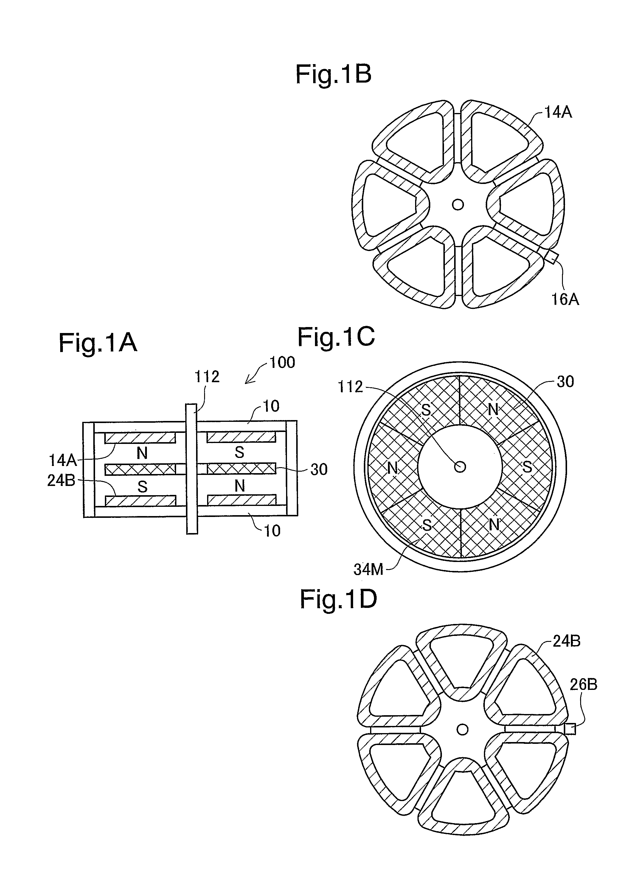
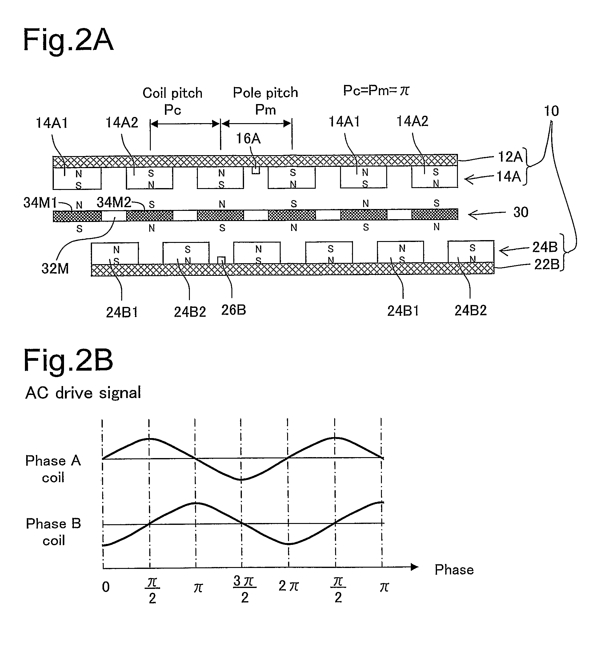
[0077]FIG. 1A is a sectional view showing the configuration of the motor unit of an electric motor in one embodiment of the present invention. This motor unit 100 has a stator unit 10 and a rotor unit 30, each of generally disk shape. The rotor unit 30 has a magnet array 34M composed of a number of magnets, and is affixed to a rotating shaft 112. The direction of magnetization of the magnet array 34M is the vertical direction. The stator unit 10 has a Phase A coil array 14A positioned above the rotor unit 30, and a Phase B coil array 24B positioned below the rotor unit 30.

[0078]FIGS. 1B to 1D depict, in detached form, the first coil array 14A of the stator unit 10, the rotor unit 30, and the second coil array 24B of the stator unit 10, respectively. In this example, the Phase A coil array 14A and the Phase B coil array 24B each have six coils; likewise, the magnet array 34M has six magnets. However, it is possible to set the number ...

embodiment 2

2. Embodiment 2

[0152]FIG. 27 is a block diagram depicting the configuration of the drive system in Embodiment 2. This drive system is furnished with multiple electric motors 100b. Here, the number of motors is denoted by M where M is an integer equal to 2 or greater. The multiple electric motors 100b are connected to a drive power supply 1200 via a power line PL, and also connected to a system controller 1300 via a control line CL. The power line PL and the control line CL are shared by the multiple electric motors 100b. Alternatively, power lines PL may be individually connected to the motors.

[0153]Each of the electric motors 100b is assigned a unique ID code (identification code) identifying it from the other electric motors. As will be discussed later, the system controller 1300 uses this ID code to send commands to individual electric motors 100b via the control line CL.

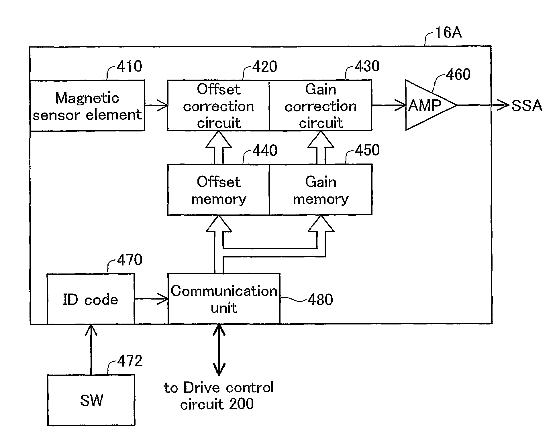
[0154]FIG. 28 is a block diagram depicting the configuration of the drive control circuit provided in each ind...

modification examples

3. Modification Examples

[0194]The present invention is not limited to the embodiments described hereinabove, and may be reduced to practice in various other ways without departing from the spirit thereof. Modifications such as the following would be possible, for example.


PUM


Abstract

The motor according to one aspect of the present invention has an output waveform correcting unit for correcting the waveform of the output signal of a magnetic sensor during operation of the electric motor. ID codes for identification purposes are assigned respectively to a plurality of magnetic sensors. The output waveform correcting unit receives, from an external device, output waveform correction values for the magnetic sensors together with the ID codes, and stores the output waveform correction values for the magnetic sensors in memory. The drive system according to another aspect of the present invention has a plurality of electric motors, and a system controller connected to the plurality of motors via a shared communication line. Each electric motor has an identification code register that stores an identification code for identifying each electric motor. The system controller has an individual control mode in which operation of individual motors is controlled by transmitting commands to individual electric motors together with identification codes via the shared communication line.

Description

TECHNICAL FIELD[0001]The present invention relates to an electric motor that utilizes permanent magnets and magnet coils, to a drive system employing multiple electric motors, and to a method for control the same.BACKGROUND ART[0002]Electric motors that utilize permanent magnets and magnet coils are known, having been disclosed in JP2001-298982A and JP2003-111483A, for example.[0003]In the prior art electric motors, motor control is carried out using an on / off signal from a digital magnetic sensor. Specifically, the timing for reversing the polarity of the voltage applied to the magnet coil is determined using the on / off signal from the digital magnetic sensor.[0004]Magnetic sensors having analog output (so-called analog magnetic sensors) are also available. However, where an analog magnetic sensor is used to control a motor, considerable error in sensor output can occur due to manufacturing errors of various kinds among motors, making it impossible in some instances to carry out mo...

Claims


Application Information

Patent Timeline
Patent Type & Authority Patents(United States)
IPC IPC(8): H02P6/16
CPCH02P5/00H02P6/006H02P29/00
Inventor TAKEUCHI, KESATOSHI
Owner PARKSIDE IP LLC
Why Eureka
Try Eureka