Apparatus and method for driving an induction motor

a technology of induction motor and apparatus, which is applied in the direction of motor/generator/converter stopper, dynamo-electric converter control, dynamo-electric gear control, etc., can solve the problems reducing the output and and reducing the changeover time. , the effect of shortening the changeover time and suppressing the variation in the speed of the induction motor upon changeover

Inactive Publication Date: 2011-03-15
HITACHI LTD
View PDF24 Cites 5 Cited by
  • Summary
  • Abstract
  • Description
  • Claims
  • Application Information

AI Technical Summary

Benefits of technology

[0006]However, the apparatus disclosed in the patent document 1 has a problem that phases of the output voltage of the inverter and the terminal voltage of the induction motor are not matched to each other and accordingly the output of the induction motor is varied depending on a phase difference therebetween, so that the changeover time until the induction motor is returned to the state before failure is lengthened. Further, the apparatus has a problem that since switches on the power side and the load side are changed over after the failure signal of one inverter is received, to initially charge the inverter to be used after changeover and at the same time after the speed of the induction motor is detected to calculate a starting frequency on the basis of the detected value, the inverter to be used after changeover is started, the changeover time is lengthened and the output and the speed of the induction motor are considerably reduced meanwhile.
[0009]It is an object of the present invention to suppress variation in output of an induction motor when one inverter is changed over to the other inverter due to failure of the one inverter to drive the induction motor.
[0011]More particularly, the frequency of the terminal voltage of the induction motor represents the speed of rotation at the time that supply of driving power to an induction motor is stopped due to failure of one inverter and the induction motor rotates inertially. Accordingly, by always detecting the terminal voltage of the induction motor, the frequency and the phase of the terminal voltage of the induction motor can be detected even during the period from the time that one inverter fails until the one inverter is changed over to another inverter. A frequency and a phase at starting of changeover of the inverter to be used after changeover can be set to be equal to the detected values to thereby synchronize the frequency and the phase of the output voltage of the inverter with the terminal voltage of the induction motor and accordingly variation in output such as variation in speed of the induction motor upon changeover can be suppressed. Further, since the frequency and the phase of the terminal voltage of the induction motor are always detected, the frequency and the phase at starting of changeover can be set simultaneously with inputting of the failure detection signal to thereby shorten the changeover time. Consequently, the inverter can be changed over to be started before the speed of the induction motor is reduced excessively, so that output variation such as torque variation of the induction motor can be minimized.
[0012]In addition to the above, it is desirable that the inverter includes an initial charging circuit having a switch which connects the inverter to the AC power supply when the circuit breaker for connecting the inverter to the AC power supply is opened, that is, when the inverter is on standby. In other words, generally, the inverter is started after the time required to charge a smoothing condenser of a DC circuit of the inverter. However, the provision of the initial charging circuit of the present invention does not require the time necessary to charge conductors of an electric circuit of the inverter to be used after changeover and accordingly the start timing of the inverter to be used after changeover can be advanced by that time. Consequently, output variation such as torque variation of the induction motor can be more minimized.
[0013]According to the present invention, when one inverter fails, the one inverter is changed over to another inverter to drive the induction motor, so that output variation of the induction motor upon changeover can be suppressed.

Problems solved by technology

However, the apparatus disclosed in the patent document 1 has a problem that phases of the output voltage of the inverter and the terminal voltage of the induction motor are not matched to each other and accordingly the output of the induction motor is varied depending on a phase difference therebetween, so that the changeover time until the induction motor is returned to the state before failure is lengthened.
Further, the apparatus has a problem that since switches on the power side and the load side are changed over after the failure signal of one inverter is received, to initially charge the inverter to be used after changeover and at the same time after the speed of the induction motor is detected to calculate a starting frequency on the basis of the detected value, the inverter to be used after changeover is started, the changeover time is lengthened and the output and the speed of the induction motor are considerably reduced meanwhile.
In addition, the apparatus disclosed in the patent document 2 has a problem that since the inverter controller is provided in common to both the inverter main circuits so that the same drive signals are always supplied to both the inverter main circuits, it is impossible to deal with the case where the inverter controller fails.

Method used


Image

  • Apparatus and method for driving an induction motor
  • Apparatus and method for driving an induction motor
  • Apparatus and method for driving an induction motor

Examples


Embodiment Construction

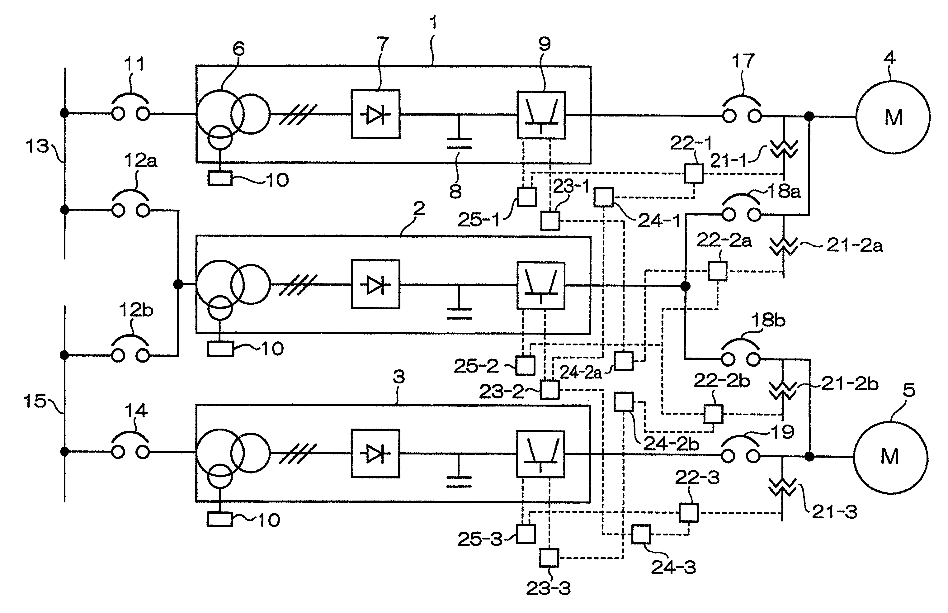
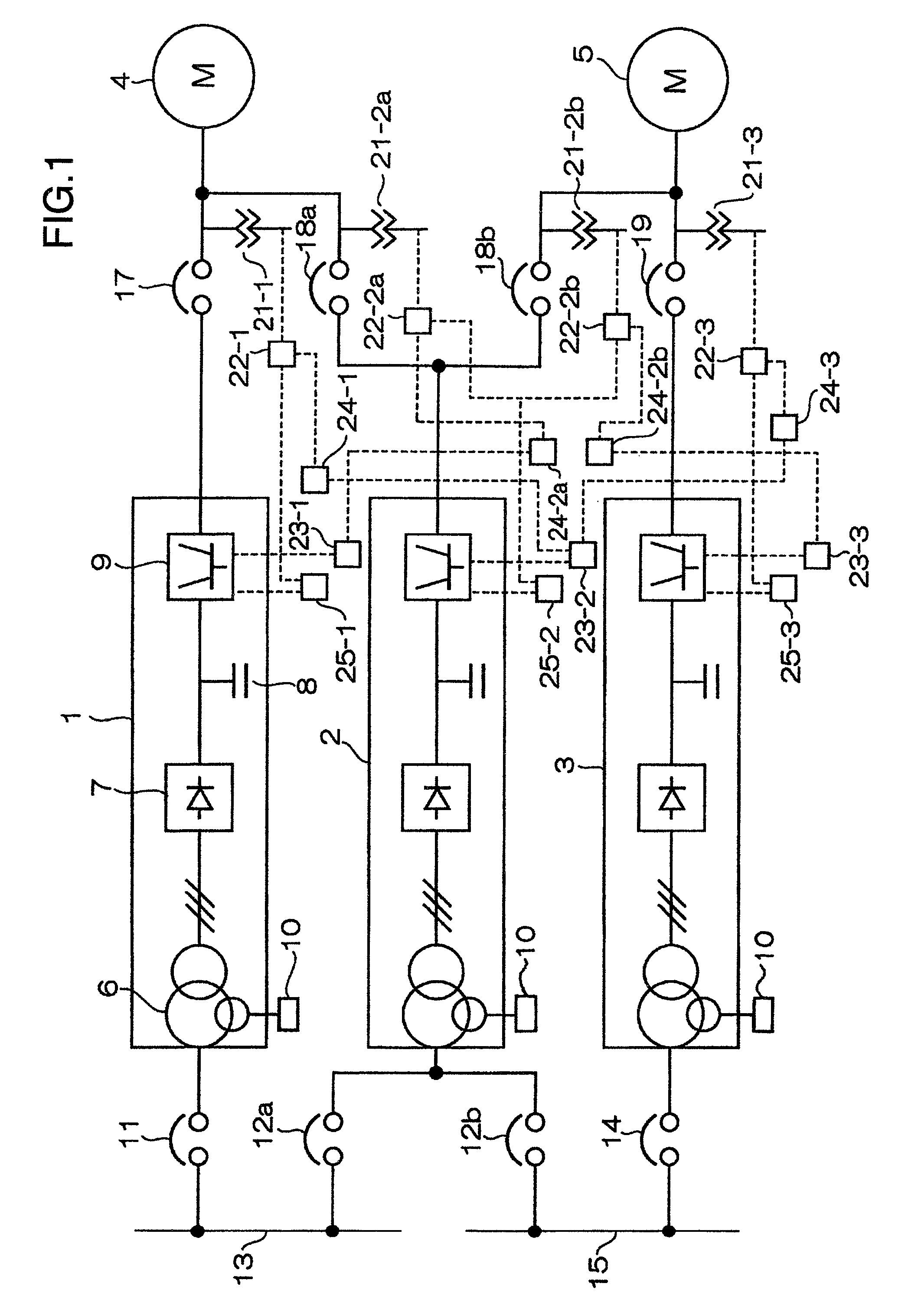
[0018]Embodiments of the present invention are now described with reference to the accompanying drawings. FIG. 1 is a block diagram illustrating an induction motor drive according to an embodiment of the present invention. As illustrated in FIG. 1, the induction motor drive of the embodiment includes three inverters 1, 2 and 3. Normally, the inverters 1 and 3 operate to drive induction motors 4 and 5, respectively, and when one of the inverters 1 and 3 fails, it can be changed over to the auxiliary inverter 2 which is provided in common to both the inverters 1 and 3. Further, when the inverter 2 fails in case where one of the induction motors 4, 5 is driven by the inverter 2, if the inverter 1 or 3 is recovered, the inverter 2 can be changed over to the inverter 1 or 3 corresponding to the induction motor 4 or 5 driven by the inverter 2.

[0019]Since the inverters 1, 2 and 3 have the same configuration, the configuration of the inverter 1 is described in detail and description of othe...


PUM


Abstract

An induction motor drive includes a plurality of inverters, a changeover switch which changes over outputs of the plurality of inverters to be supplied to one induction motor and a changeover controller which controls the changeover switch on the basis of a failure detection signal of one inverter to change over from the one inverter to another inverter to start the other inverter so that the induction motor is driven. The changeover controller includes a frequency / phase detector which always detects a frequency and a phase of a terminal voltage of the induction motor and a starting frequency / phase setting device which controls a frequency and a phase at starting of the other inverter in accordance with detected values of the frequency / phase detector when the failure signal is inputted.

Description

BACKGROUND OF THE INVENTION[0001]The present invention relates to an induction motor drive which carries out adjustable speed operation of an induction motor by an inverter and more particularly to technique effective when one inverter fails and the inverter is changed over from the failed inverter to another inverter to drive the induction motor.[0002]The induction motor drive for carrying out adjustable speed operation of the induction motor by the inverter is widely used to carry out adjustable speed operation of various machines (hereinafter referred to as load) such as fan and pump. Further, in case of an important load which is not allowed to be stopped even if failure occurs, inverters are duplexed and when one inverter fails, the inverter is changed over from the failed inverter to the other inverter to continue the adjustable speed operation without stopping operation of the load.[0003]For example, in an induction motor drive described in JP-A-5-336787 (patent document 1), ...

Claims


Application Information

Patent Timeline
Patent Type & Authority Patents(United States)
IPC IPC(8): H02P27/04H02P21/34H02P23/07H02P27/06
CPCH02P27/04
Inventor TAN, DAISUKESATOMI, HIROHISAOKAMATSU, SHIGETOSHIMIYAZAKI, KOICHI
Owner HITACHI LTD
Why Eureka
Try Eureka