Tolerable synchronization circuit of RDS receiver

a synchronization circuit and receiver technology, applied in the field of synchronization circuit of rds decoder, can solve the problems of radio receivers having difficulty locking onto the rds subcarrier signal based, rds subcarrier may not be exactly the third,

Inactive Publication Date: 2011-03-15
HIMAX TECH LTD
View PDF3 Cites 16 Cited by
  • Summary
  • Abstract
  • Description
  • Claims
  • Application Information

AI Technical Summary

Benefits of technology

[0010]According to another exemplary embodiment of the claimed invention, a method of radio data system (RDS) decoding is disclosed, which includes determining an RDS subcarrier frequency utilizing only an RDS signal of an FM broadcast signal.

Problems solved by technology

The undesired result is that the RDS subcarrier may not be exactly the third harmonic of the pilot tone.
For example, if the pilot tone is substantially under the typical 19 kHz and the RDS subcarrier is slightly higher than the normal 57 kHz, a radio receiver may have difficulties locking onto the RDS subcarrier signal based on the received pilot tone.
This difficulty is also possible when each modulator experiences differing frequency drift, particularly in opposite directions.
Consequently, the radio receivers experiencing the above problems will exhibit poorer reception of the RDS signal, and reduced performance in providing RDS data to the user.

Method used


Image

  • Tolerable synchronization circuit of RDS receiver
  • Tolerable synchronization circuit of RDS receiver
  • Tolerable synchronization circuit of RDS receiver

Examples


Embodiment Construction

[0023]Certain terms are used throughout the following description and claims to refer to particular system components. As one skilled in the art will appreciate, manufacturers may refer to a component by different names. This document does not intend to distinguish between components that differ in name but not function. In the following discussion and in the claims, the terms “including” and “comprising” are used in an open-ended fashion, and thus should be interpreted to mean “including, but not limited to . . . ” The terms “couple” and “couples” are intended to mean either an indirect or a direct electrical connection. Thus, if a first device couples to a second device, that connection may be through a direct electrical connection, or through an indirect electrical connection via other devices and connections.

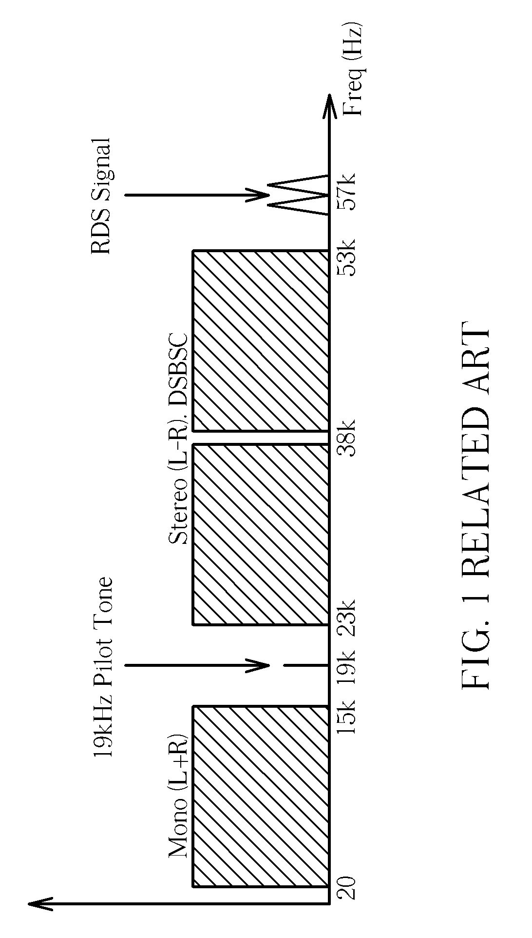
[0024]FIG. 1 shows a typical bandwidth diagram of frequency modulated (FM) broadcast spectrum. Of particular note is that a 19 kHz pilot tone is utilized for stereo broadcas...


PUM


Abstract

A Radio Data System (RDS) decoder circuit determines a subcarrier frequency utilizing only a 57 kHz RDS signal of an FM broadcast signal. The RDS decoder includes a zero-intermediate frequency (zero-IF) FM demodulator, a first mixer, a low-pass filter (LPF) unit, a shaping filter unit, a carrier recovery circuit, a digitally controlled oscillator (DCO), a symbol timing recovery circuit, an integrate and dump circuit, a slicer 280, and a differential decoder. The carrier recovery circuit includes a phase error detector and a digital loop filter (DLF). The symbol timing recovery circuit includes a zero-crossing detector, a phase detector and loop filter unit, and a counter.

Description

BACKGROUND OF THE INVENTION[0001]1. Field of the Invention[0002]The present invention relates to a synchronization circuit of an RDS decoder, and more particularly, a subcarrier recovery circuit and symbol timing recovery circuit of an RDS decoder and related methods thereof.[0003]2. Description of the Prior Art[0004]Radio Data System (RDS) is a standard from the European Broadcasting Union for sending digital information using conventional FM (frequency modulation) radio broadcasts. Radio Broadcast Data System (RBDS) is the official name used for the North American version of RDS, but is also commonly referred to as RDS. The RDS system standardizes several types of information transmitted and uses a 57 kHz subcarrier, which was chosen for being the third harmonic (3×) of the 19 kHz pilot tone for FM stereo.[0005]To decode the RDS signal, a typical radio receiver first locks onto the received pilot tone and then calculates the third harmonic of the pilot tone frequency (19 kHz) to f...

Claims


Application Information

Patent Timeline
Patent Type & Authority Patents(United States)
IPC IPC(8): H03K9/00H04L27/00
CPCH04H40/18H04H2201/13
Inventor TSAI, TIEN-JULIN, CHIH-FENGLU, SHIH-CHUAN
Owner HIMAX TECH LTD
Why Eureka
Try Eureka