Joint for use in aircraft construction

a technology for aircraft construction and joints, applied in aircraft accessories, aircraft floors, wings, etc., can solve the problems of increasing overhang size, adversely affecting the mechanical properties of laminates, and impractical direct attachment of leading and trailing edge structures to wing skins

Active Publication Date: 2011-03-22
AIRBUS OPERATIONS LTD
View PDF14 Cites 34 Cited by
  • Summary
  • Abstract
  • Description
  • Claims
  • Application Information

AI Technical Summary

Benefits of technology

[0027]It may be that cut edges of the leading edge of the skin are protected, at least partially by the butt-strap, so that they are not exposed to the air stream in flight.

Problems solved by technology

Direct attachment of leading and trailing edge structures, such as leading and trailing edge panels, to the wing skin is often impractical when using laminates.
Pre-moulded precision-fit joints, known as joggles, are difficult to manufacture in thick laminates, would increase overhang size and may adversely affect the mechanical properties of the laminate.
Furthermore, it is difficult to provide effective panel attachment through thick laminates.
However, it is found that aerodynamic erosion still occurs and the increased thickness also increases drag.
Aerodynamic erosion is often exacerbated when composite materials are used.

Method used


Image

  • Joint for use in aircraft construction
  • Joint for use in aircraft construction
  • Joint for use in aircraft construction

Examples


Embodiment Construction

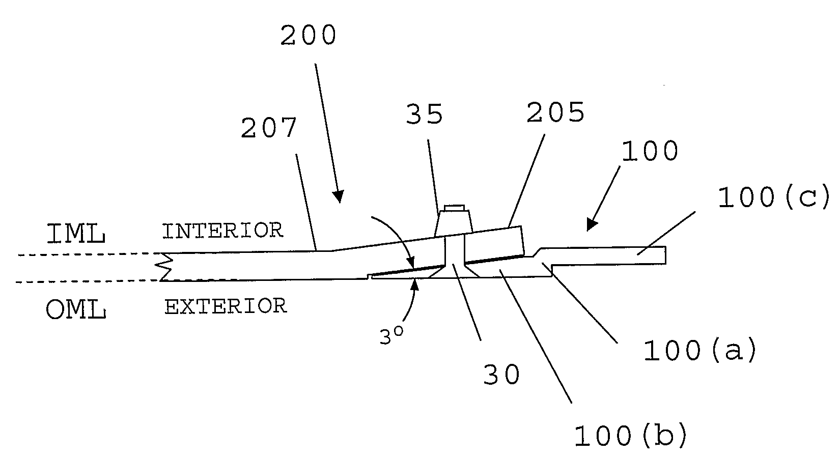
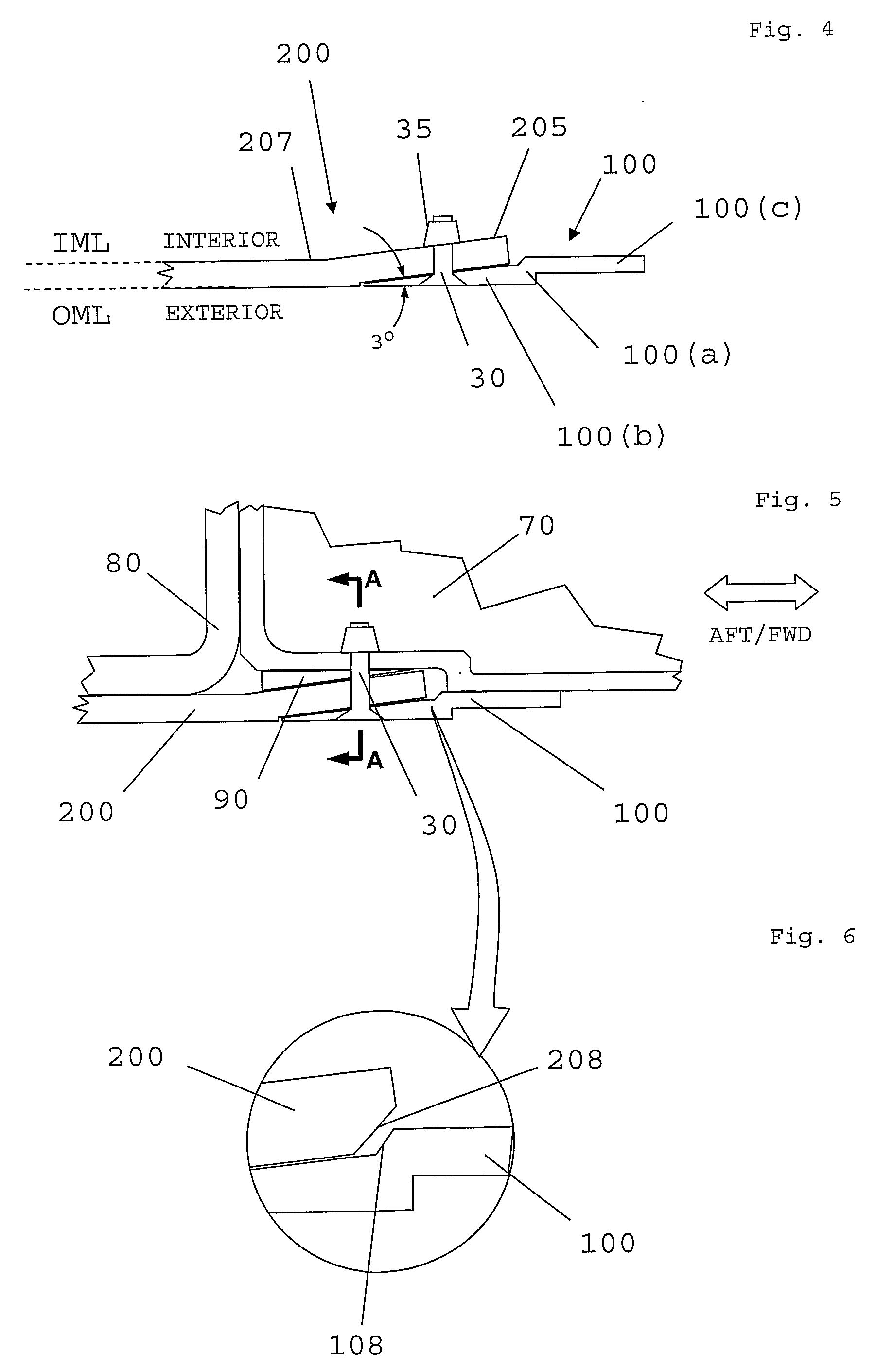
[0050]Referring to FIG. 4, an embodiment of a butt-strap 100 is shown in profile and is seen to be in the form of a mildly stepped, z-shaped profile, with a short vertical portion 100a joining two horizontal plate portions 100b,c. According to this embodiment, plate 100b has a wedge-shaped profile, tapering from its thickest point near the vertical portion 100a to a thin, distal end. In a preferred variant, the thickness of the first portion at the junction formed by the exterior surface of the cover skin at the exterior surface of the butt-strap (i.e.; the distal end) is zero. When the joint is created, this would form an essentially perfect planar seam joining the cover and the butt-strap. However, in practice, most practical embodiments will have a small, but non-zero thickness at the distal end of the first portion such as shown in FIG. 4. According to this particular embodiment, the interior, tapering surface forms an angle of about 3° with the exterior face of plate 100b.

[005...


PUM


Abstract

A joint for use in aircraft construction, for example a wing, comprises: a cover skin having an interior surface, an exterior surface and a distal portion, said distal portion having an exterior-facing surface; and a butt-strap having a first portion for connection to the skin, said first portion having an interior surface, an exterior surface and a distal end. The first portion of the butt-strap is connected to the distal portion of the skin such that a junction is formed between the exterior surface of the skin and the exterior surface of the first portion of the butt-strap. The exterior-facing surface of the distal portion of the skin is of a shape complementary to the shape of the interior surface of the first portion of the butt-strap. The first portion of the butt-strap tapers towards its distal end such that, at said junction, the exterior surface of the skin and the exterior surface of the first portion of the butt-strap form a substantially continuous exterior surface.

Description

RELATED APPLICATIONS[0001]The present application is based on International Application Number PCT / GB2006 / 004439 filed Nov. 28, 2006, and claims priority from British Application Number 0525896.7 filed Dec. 20, 2005, the disclosures of which are hereby incorporated by reference herein in their entirety.FIELD OF THE INVENTION[0002]The present invention relates to an improved joint arrangement suitable for use in aircraft construction. More particularly, although not exclusively, the present invention relates to an improved cover skin joint construction which is particularly suitable for joining aircraft components which have dissimilar physical properties. Even more particularly, although not exclusively, the present invention relates to an improved butt-strap and wing-skin cover joint for use in an aircraft wing for joining composites and metals.BACKGROUND ART[0003]Aircraft components including items such as wing skins and other panels are increasingly being made from composite mate...

Claims


Application Information

Patent Timeline
Patent Type & Authority Patents(United States)
IPC IPC(8): B64C1/12
CPCB64C1/12B64C3/26
Inventor COOPER, PAUL ANTHONY
Owner AIRBUS OPERATIONS LTD
Why Eureka
Try Eureka