Lighting system

a technology of light source and light source, which is applied in the direction of discharge tube/lamp details, fixed transformers or mutual inductances, and inductances, etc., can solve the problems of high cost, short-circuit risk or shock danger, and the conventional solution of electric contacts is subject to pollution or humidity, etc., to achieve less restrictions, improve the magnetic flux density of the coil winding, and the effect of higher output voltag

Active Publication Date: 2011-03-22
SIGNIFY HLDG BV
View PDF21 Cites 20 Cited by
  • Summary
  • Abstract
  • Description
  • Claims
  • Application Information

AI Technical Summary

Benefits of technology

[0015]A further advantage of the present invention is that the base part with its substrate and the electronic components thereon may be formed very compactly allowing to integrate the base part in quite a lot of objects, for example a textile, a wallpaper, a mirror, a curtain or a floor covering, which are generally very thin objects.
[0016]In general, the inventive solution enables to design a lighting system with less restrictions compared to former solutions.
[0017]In a preferred embodiment the base part comprises a plurality of primary coils, preferably arranged as an array, defining a plurality of preferably similar coupling areas.
[0018]With other words, the base part comprises a plurality of coupling areas which are arranged like a chessboard as one example. Of course other forms, whether rectangular or circular, are also conceivable. The light module with its flat surface may be put on any of the plurality of similar coupling areas so that the designer or user of the lighting system has a variety of possibilities to arrange one or more light modules.
[0019]In a further preferred embodiment, said base part and / or said light module comprise a soft-magnetic plate.
[0020]This measure has the advantage that the magnetic field of the coils is shielded from the remaining circuits and the magnetic flux density in the winding of the coils is improved to gain a higher output voltage and a better coupling. The soft-magnetic material can be a ferrite plate, a μ-metal, etc., however, preferably it consists of a material that can be laminated to a printed circuit board, e.g. a plastic ferrite compound or structured high permeable metal foil.

Problems solved by technology

As a problem, devices with LEDs or OLEDs need to be powered or their batteries need to be recharged.
In many environments, a conventional solution with electric contacts is subjected to pollution or to humidity.
Additionally, open electric contacts cause short-circuit risks or shock danger.
However, standard drivers are bulky.

Method used


Image

  • Lighting system
  • Lighting system
  • Lighting system

Examples


Embodiment Construction

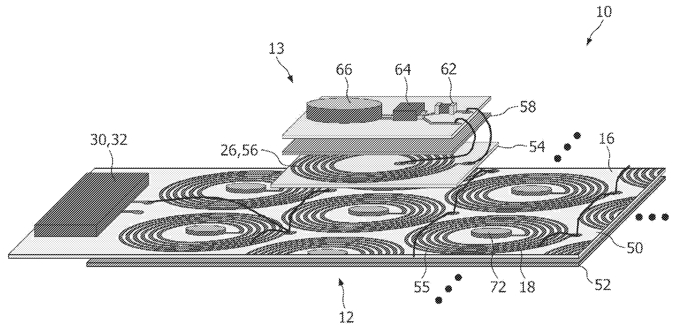
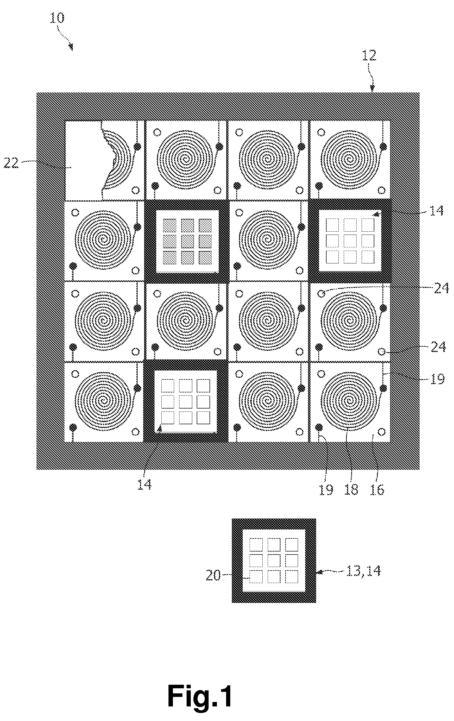
[0054]In FIG. 1 an embodiment of a lighting system is schematically shown and indicated with reference number 10. It is to be noted that the schematic diagram of the lighting system 10 is just for illustration purposes as to describe those technical features necessary for understanding the invention.

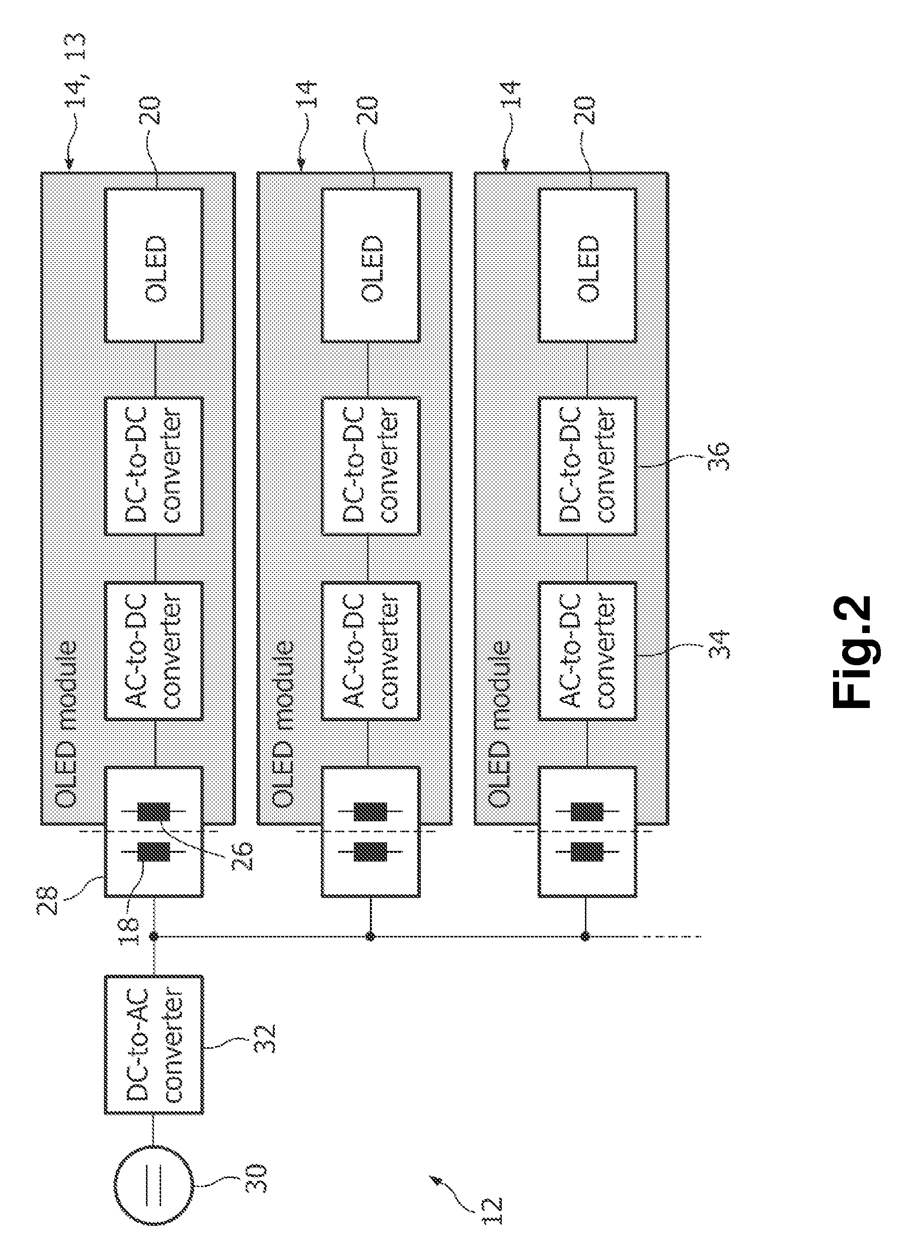
[0055]The lighting system 10 substantially consists of two main parts, namely a base part 12 and at least one light module 13. In the present embodiment, the light modules are provided as organic light-emitting diode modules 14 (in the following OLED module). Organic light-emitting diodes are well-known in the art and gain more and more interest due to their reduced power requirements compared to for example LCDs, their form factor, their flexibility, and the possibility to provide nearly all colours. In other embodiments, the light modules 14 may be LED modules.

[0056]In the present embodiment, the base part 12 comprises a rectangularly shaped frame for holding a printed circuit board 50...


PUM

PropertyMeasurementUnit
frequencyaaaaaaaaaa
AC voltageaaaaaaaaaa
voltageaaaaaaaaaa

Abstract

The present invention relates to a lighting system comprising a base part (12) with at least one primary coil (18), and at least one light module (13, 14) with a secondary coil (26) adapted to inductively interact with the primary coil (18). The lighting system is characterized in that said base part (12) comprises a substrate (50) carrying said primary coil (18), the winding of which lying in one plane and forming a flat coupling area (16); the winding of the second coil (26) lies in one plane; and said light module (13, 14) comprises at least one light element (20) and a flat bottom surface, so that the light module (13, 14) is placeable with its flat surface on the flat coupling area (16).

Description

[0001]This application is a national stage application under 35 U.S.C. §371 of International Application No. PCT / IB2007 / 051913 filed on May 21, 2007, and published in the English language on Jan. 31, 2008, as International Publication No. WO / 2008 / 012702, which claims priority to European Application No. 06117675.6, filed on Jul. 21, 2006, incorporated herein by reference.FIELD OF THE INVENTION[0002]The present invention relates to a lighting system comprising a base part with at least one primary coil, and at least one light module with a secondary coil adapted to inductively interact with the primary coil.BACKGROUND OF THE INVENTION[0003]In the art, for example from document EP 1 319 889 A1, it is known to energize a light-emitting diode inductively by using a primary coil and a secondary coil connected with the LEDs.[0004]Generally, wireless powering and / or charging systems are frequently used in many applications. They allow powering of devices or charging of batteries (or capaci...

Claims


Application Information

Patent Timeline
Patent Type & Authority Patents(United States)
IPC IPC(8): F21L13/06H01F27/42
CPCF21V23/02H01F27/2804H01F38/14H02J7/025H05B33/0803H05B33/0815H05B33/0851H05B33/0896H02J5/005F21Y2101/02H01F19/04F21Y2105/008F21Y2105/00F21Y2115/15H05B45/60H05B45/37H05B45/00H02J7/0042Y02B20/30H02J50/402H02J50/12H02J50/005H05B45/10
Inventor JACOBS, JOSEPH HENDRIK ANNA MARIAWAFFENSCHMIDT, EBERHARDHENTE, DIRKBRAGARD, MICHAELBUDDE, WOLFGANG OTTO
Owner SIGNIFY HLDG BV
Why Eureka
Try Eureka