Lighting system for creating an illuminated surface

a technology of illumination system and illumination surface, which is applied in the field of illumination system, can solve the problems of inability to compensate effects, inability to use edge lighting, and inability to provide edge lighting, so as to achieve uniform illumination effect, the effect of limiting the maximum panel size of the edge lighting

Inactive Publication Date: 2011-03-22
KONINK PHILIPS ELECTRONICS NV
View PDF22 Cites 66 Cited by
  • Summary
  • Abstract
  • Description
  • Claims
  • Application Information

AI Technical Summary

Problems solved by technology

Large bodies capable of uniformly generating and emitting light across an extended two-dimensional surface, for example, light-emitting foils which can be used in panel or back lighting systems, are presently unavailable.
However, edge lighting limits the maximum panel size which can be uniformly illuminated because of light attenuation and aberration due to optical effects inside and at the edge of the panel or light guide.
For various reasons, these effects cannot be compensated by providing increased amounts of light at the edge of the light guide to build substantially arbitrarily large panels.
Furthermore, the placement of light-extracting elements needs to be customized for the size of the panel which economically impedes arbitrary panel size scaling.
The state of the art in display systems however, does not provide technological or economic solutions for architectural lighting, for which large surfaces need to be illuminated.

Method used


Image

  • Lighting system for creating an illuminated surface
  • Lighting system for creating an illuminated surface
  • Lighting system for creating an illuminated surface

Examples


examples

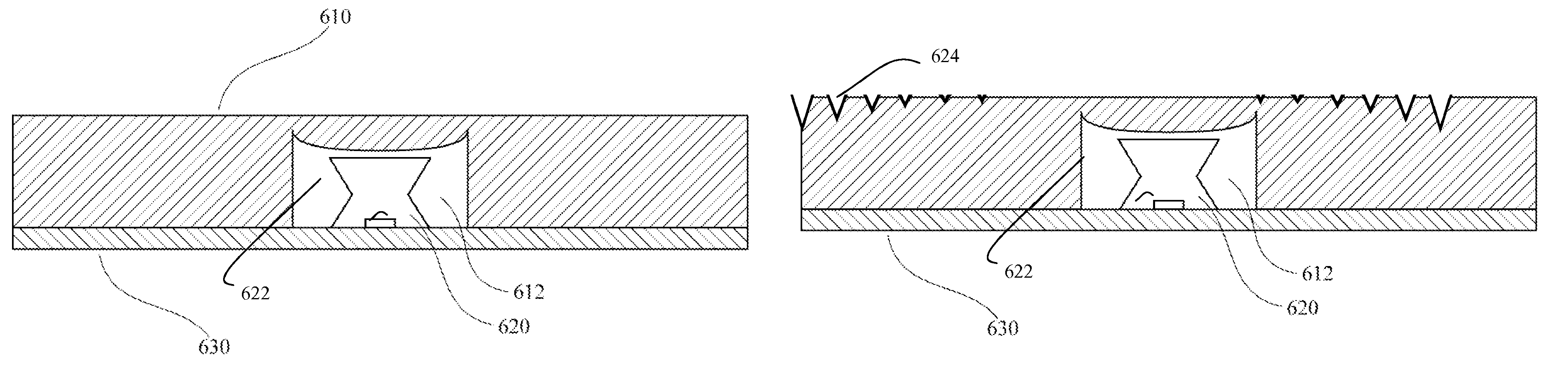
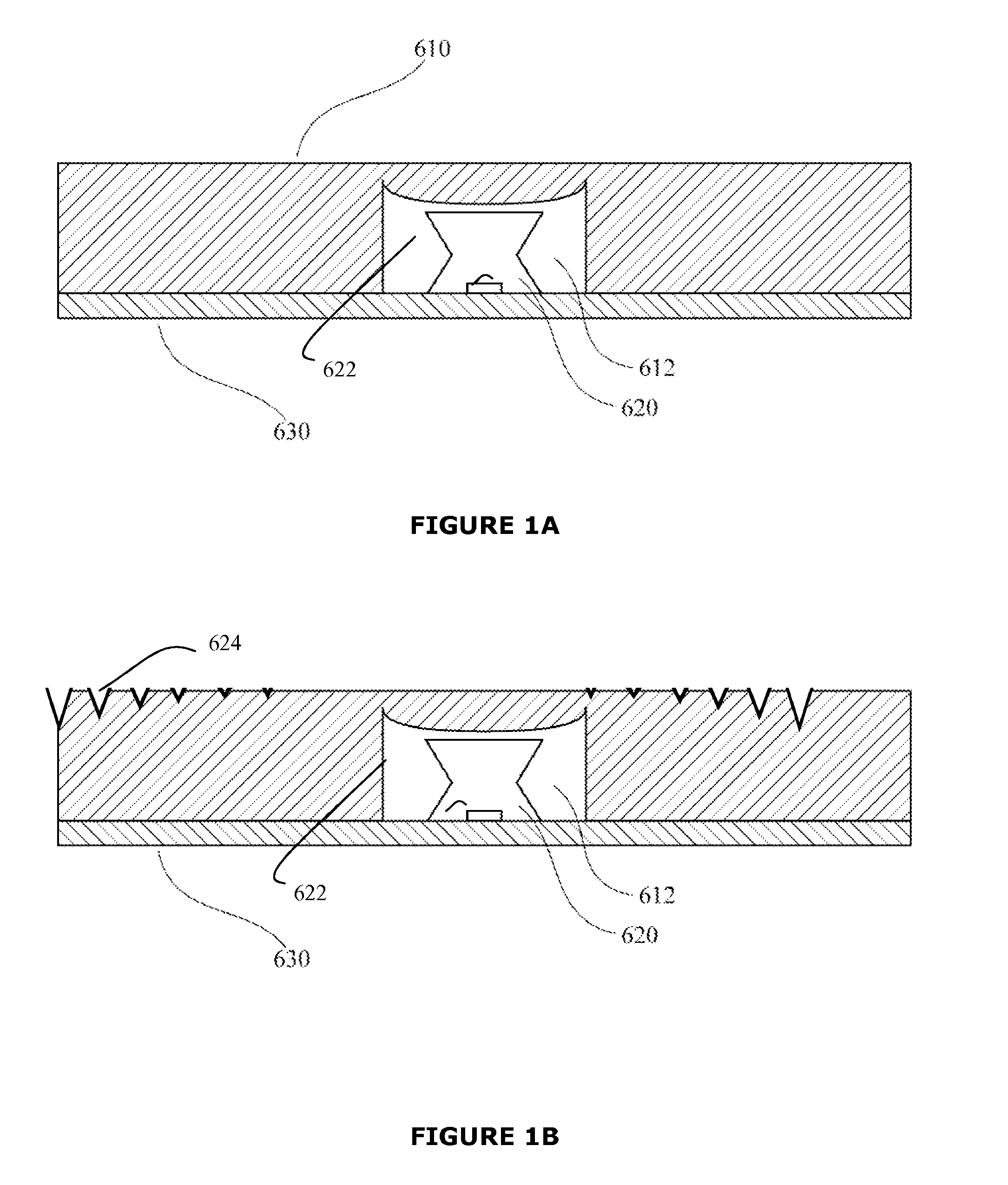
[0058]FIG. 1A illustrates an elevational cross section of an embodiment of the lighting system according to the present invention. The lighting system comprises a light-transmissive sheet or light guide 610 which defines a hole 612. In addition, the lighting system comprises a side light-emitting element 620 positioned within the hole in order to substantially maximize light extraction into the light-transmissive sheet. The light-emitting element 620 is affixed to a substrate 630 which provides traces and pathways for the supply of electronic signals and power to the light-emitting element. The traces and pathways are not illustrated. A primary optic 622 is optically coupled to the light-emitting element 620 enabling the redirection of the light sideways. The light redirecting elements can be formed between the light-transmissive sheet and the substrate (not shown) or can be formed on the top of the light-transmissive sheet as illustrated in FIG. 1B. In one embodiment, the light red...


PUM


Abstract

The present invention combines point light sources in combination with a light guide element and light redirecting elements into a system which can emit light across one or more extended surfaces of the light guide and may be designed to be able to emit light uniformly across the extended surfaces. The system comprises one or more light-emitting elements and a light guide in which are defined one or more voids. The light-emitting elements are optically coupled to the light guide by positioning them adjacent to a surface of the light guide, or by positioning them proximal to one or more of the voids. One or more light-emitting elements can be optically coupled to one void such that they emit light into the light guide substantially through that void and not through any other void of the one or more voids. Optically coupled to the light guide are a plurality of light redirecting elements for altering of the propagation of light through the light guide, thereby enabling light to be emitted from the surface of the light guide in a desired pattern, for example in a uniform illumination pattern.

Description

CROSS-REFERENCE TO RELATED APPLICATIONS[0001]This application is a national stage application under 35 U.S.C. §371 of International Application No. PCT / CA2007 / 000130 filed on Feb. 1, 2007 and published in the English language on Aug. 9, 2007 as International Publication No. WO2007 / 087710, which claims priority to (i) U.S. Provisional Application Ser. No. 60 / 763,966, filed on Feb. 1, 2006 and (ii) U.S. Provisional Application Ser. No. 60 / 826,097, filed on Sep. 19, 2006, all of which are hereby incorporated herein by reference.FIELD OF THE INVENTION[0002]The present invention pertains to lighting systems and in particular to a lighting system for creating an illuminated surface.BACKGROUND[0003]Large bodies capable of uniformly generating and emitting light across an extended two-dimensional surface, for example, light-emitting foils which can be used in panel or back lighting systems, are presently unavailable. However, light guides are common elements in contemporary display and ligh...

Claims


Application Information

Patent Timeline
Patent Type & Authority Patents(United States)
IPC IPC(8): F21V7/04
CPCG02B6/0021G02B6/0038G02B6/0041G02B6/0046G09F13/22G09F13/04G09F13/18G02F2001/133607G02F1/133603G02F1/133607
Inventor MATHESON, GEORGE ESPEIER, INGO
Owner KONINK PHILIPS ELECTRONICS NV
Why Eureka
Try Eureka