Information processing apparatus and information processing method

a technology of image sensing device and information processing apparatus, which is applied in the field of can solve the problems of convergent to an error value, inability to correctly recognize the correspondence between a measurement line segment and an edge, and inability to search for edge segments in overlapping search areas. to achieve the effect of accurately associating and accurately measuring the position and orientation of an image sensing devi

Active Publication Date: 2011-03-22
CANON KK
View PDF4 Cites 17 Cited by
  • Summary
  • Abstract
  • Description
  • Claims
  • Application Information

AI Technical Summary

Benefits of technology

[0024]The present invention has been made in consideration of the above-described problems, and has as its object to provide a technique of accurately associating a measurement line segment of a measurement target object and an edge of the measurement target object on a sensed image and more accurately measuring the position and orientation of an image sensing device using the correspondence relationship.

Problems solved by technology

If the correspondence between measurement line segments and edges is insufficient, the difference between a measurement line segment and the edge of another measurement line segment may be calculated, and the solution may converge to an erroneous value.
In this case, an edge search process in the overlapping search areas is useless.
For this reason, near a corner of the measurement target object or for parallel measurement line segments in close vicinity on the sensed image, it may be impossible to correctly recognize the correspondence between a measurement line segment and an edge.
The correspondence relationship between a detected edge and a measurement line segment is often erroneously recognized, affecting the position and orientation estimation result.

Method used


Image

  • Information processing apparatus and information processing method
  • Information processing apparatus and information processing method
  • Information processing apparatus and information processing method

Examples


first embodiment

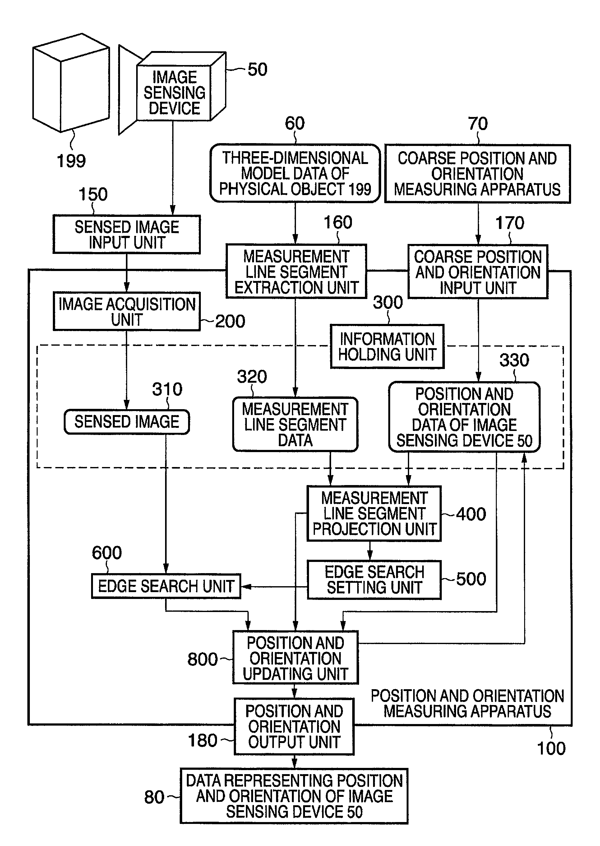
[0053]FIG. 1 is a block diagram showing the functional arrangement of a system including a position and orientation measuring apparatus 100 which measures the position and orientation of an image sensing device 50 and to which an information processing apparatus according to this embodiment is applied. As shown in FIG. 1, the system of this embodiment includes the image sensing device 50, position and orientation measuring apparatus 100, and coarse position and orientation measuring apparatus 70. These units will be described below with reference to FIG. 1.

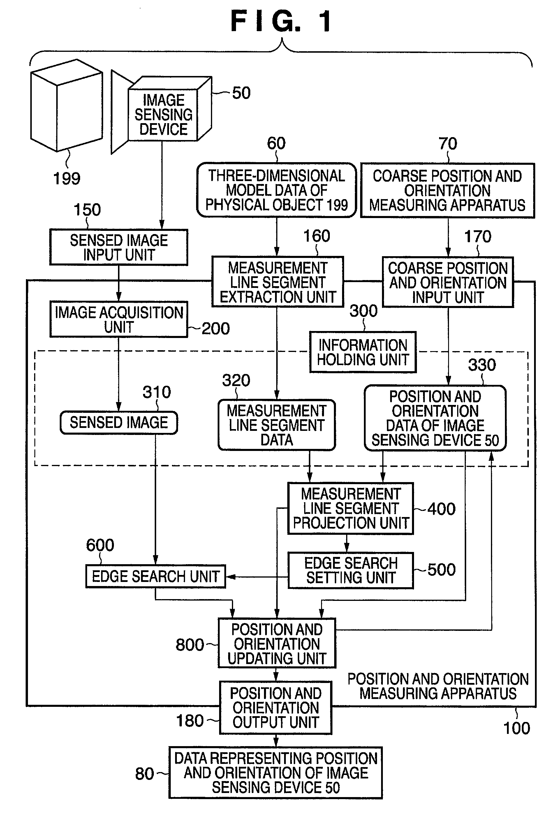
[0054]A physical object 199 having an arbitrary shape formed from polygonal planes is arranged in a physical space as a measurement target object. In FIG. 1, the physical object 199 is a rectangular parallelepiped. However, the shape is not limited to this.

[0055]The image sensing device 50 senses a moving image of the physical space including the physical object 199 and sequentially inputs the sensed frame images (to be referred t...

second embodiment

[0160]In the second embodiment, a case in which the position and orientation measuring apparatus 100 described in the first embodiment is applied to a system for presenting a mixed reality to a user will be described.

[0161]FIG. 9 is a block diagram showing the functional arrangement of a system according to this embodiment. The same reference numerals as in FIG. 1 denote the same parts in FIG. 9.

[0162]Referring to FIG. 9, a physical object 10 is a solid object formed from polygonal planes. An image sensing device 50 senses a moving image of a physical space including the physical object 10 and inputs the frame images to a chromakey composition device 920 via an image input unit 921 and also to a position and orientation measuring apparatus 100 via a sensed image input unit 150.

[0163]In the position and orientation measuring apparatus 100, three-dimensional model data corresponding to the physical object 10 is registered in place of the three-dimensional model data 60. The data struc...

third embodiment

[0173]In the first embodiment, all the units included in the position and orientation measuring apparatus 100 shown in FIG. 1 are formed from hardware. However, some of the units may be formed from software. For example, an information holding unit 300 may be implemented as a memory. Input units 150 and 170, an extraction unit 160, and an output unit 180 may be implemented by I / Fs (interfaces). The remaining units may be implemented by software.

[0174]In this case, the software is stored in a memory provided in a general PC (Personal Computer) and executed by the CPU of the PC. When some of the units of the position and orientation measuring apparatus 100 show in FIG. 1 are implemented by software in this way, the computer for executing the software is applicable to the position and orientation measuring apparatus 100.

[0175]FIG. 12 is a block diagram showing the hardware configuration of a computer applicable to the position and orientation measuring apparatus 100.

[0176]A CPU 1201 co...


PUM


Abstract

A measurement line segment projection unit (400) projects, onto a sensed image, a three-dimensional model which is arranged at the position and orientation of a physical object (199). A search range is set for each side of the virtual object projected onto the sensed image, near the side of the virtual object in the sensed image based on a positional relationship between the side and other sides of the virtual object. A side of the physical object (199) on the sensed image is searched for within the search range for each side of the virtual object. The position and orientation relationship between the physical object (199) and an image sensing device (50) is calculated using the correspondence relationship, determined based on the search result, between each side of the three-dimensional model projected onto the sensed image and each side of the physical object (199) located on the sensed image.

Description

BACKGROUND OF THE INVENTION[0001]1. Field of the Invention[0002]The present invention relates to a technique of measuring the position and orientation of an image sensing device.[0003]2. Description of the Related Art[0004]In a mixed reality system which presents an image formed by synthesizing, for example, a physical space with a virtual space to a user, it is necessary to measure the position and orientation of an image sensing device for sensing the physical space.[0005]As a method of measuring the position and orientation of an image sensing device, conventionally, a method using an index whose three-dimensional position is known has been disclosed. In this method, the position and orientation of an image sensing device are estimated by optimizing an objective function which uses the distance between a projection position where the three-dimensional position of an index is projected onto a sensed image using the coarse position and orientation of the image sensing device and th...

Claims


Application Information

Patent Timeline
Patent Type & Authority Patents(United States)
IPC IPC(8): H04N5/228H04N5/225G06K9/36G06K9/00
CPCG06T7/0042H04N5/2224H04N5/272H04N17/002G06T2207/30244G06T7/73
Inventor KOBAYASHI, KAZUHIKO
Owner CANON KK
Why Eureka
Try Eureka